00192169-01.pdf - 第15页
Order No. 00192 169-01 User Manual - Productivity Lift E_SPLFS03_V40_11_0300_200300_V1_14.doc Last update: 20.03.2000 - Version V 1.14 Page 15 3.5 Transport and assembly locks 3.5.1 Disconnecting compressed air supply WA…

Order No. 00192 169-01 User Manual - Productivity Lift
E_SPLFS03_V40_11_0300_200300_V1_14.doc Last update: 20.03.2000 - Version V 1.14 Page 14
3.4 ESD guidelines
Please comply with the notes concerning the ESD guidelines as they are specified in the
operating instructions of the placement machine.
Order No. 00192 169-01 User Manual - Productivity Lift
E_SPLFS03_V40_11_0300_200300_V1_14.doc Last update: 20.03.2000 - Version V 1.14 Page 15
3.5 Transport and assembly locks
3.5.1 Disconnecting compressed air supply
WARNING
Do not loosen a compressed air line without making sure that the corresponding air service
unit is pressureless by opening the handslide discharge valve or alternatively by closing the
main valve of the compressed air supply.
3.5.2 Locking the lift belt
WARNING
The installation aid shown in the figures serves to lock the lift during servicing, maintenance
work, for example, when changing the toothed belt, and during transport. Any activity that
involves a person having to intervene in the lift area in any way should result in the following
locking measures being taken as described below. After the activities are finished and before
the device is turned on again all securities have to be removed and to be deposed at the right
place.
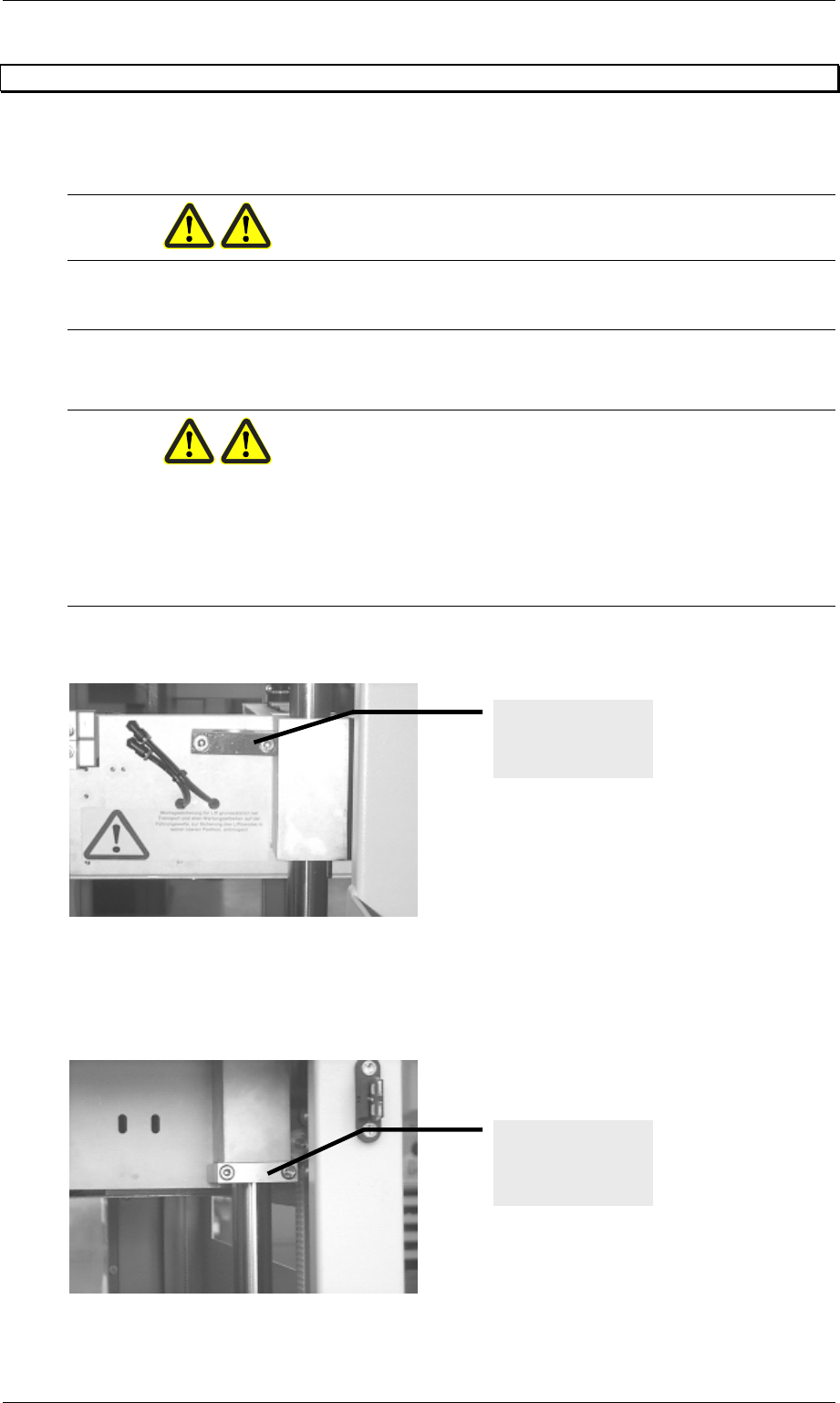
1. The following picture shows where the installation aid is kept when it is not in use.
Figure 2: Lift belt installation aid in its storage place
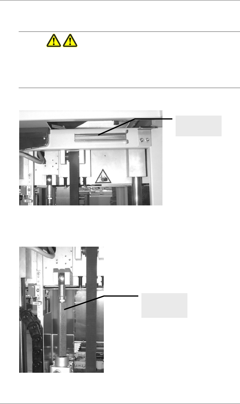
2. Before carrying out any work that is required at either of the two lift units, the installation
lock must be secured as shown in the figure below on the guide shaft underneath the lift.
To this end, the lift must be transported to its uppermost position.
Figure 3: Lift belt installation aid mounted
Installation aid in
its storage place
Locking the lift unit
using the
installation aid.
Order No. 00192 169-01 User Manual - Productivity Lift
E_SPLFS03_V40_11_0300_200300_V1_14.doc Last update: 20.03.2000 - Version V 1.14 Page 16
3.5.3 Locking the upper lift belt
WARNING
The installation aid shown in the figures serves to lock the upper lift belt during servicing,
maintenance work and transport. Any activity that involves a person having to intervene in any
way in the area between the upper lift belt and the lift belt should result in the following locking
measures being taken as described below. After the activities are finished and before the
device is turned on again all securities have to be removed and to be deposed at the right
place.
1. The following picture shows where the installation aid is kept when it is not in use.
Figure 4: Locking the upper lift belt in its storage position
2. Before carrying out any work that is required at either of the two lift units, the installation
lock must be press-fitted as shown in the figure below on the piston rod of the cylinder. To
this end, the lift must be transported to its uppermost position.
Figure 5: Upper lift belt lock mounted
Installation aid in
its storage place
Locking the lift unit
using the
installation aid.