00192169-01.pdf - 第23页
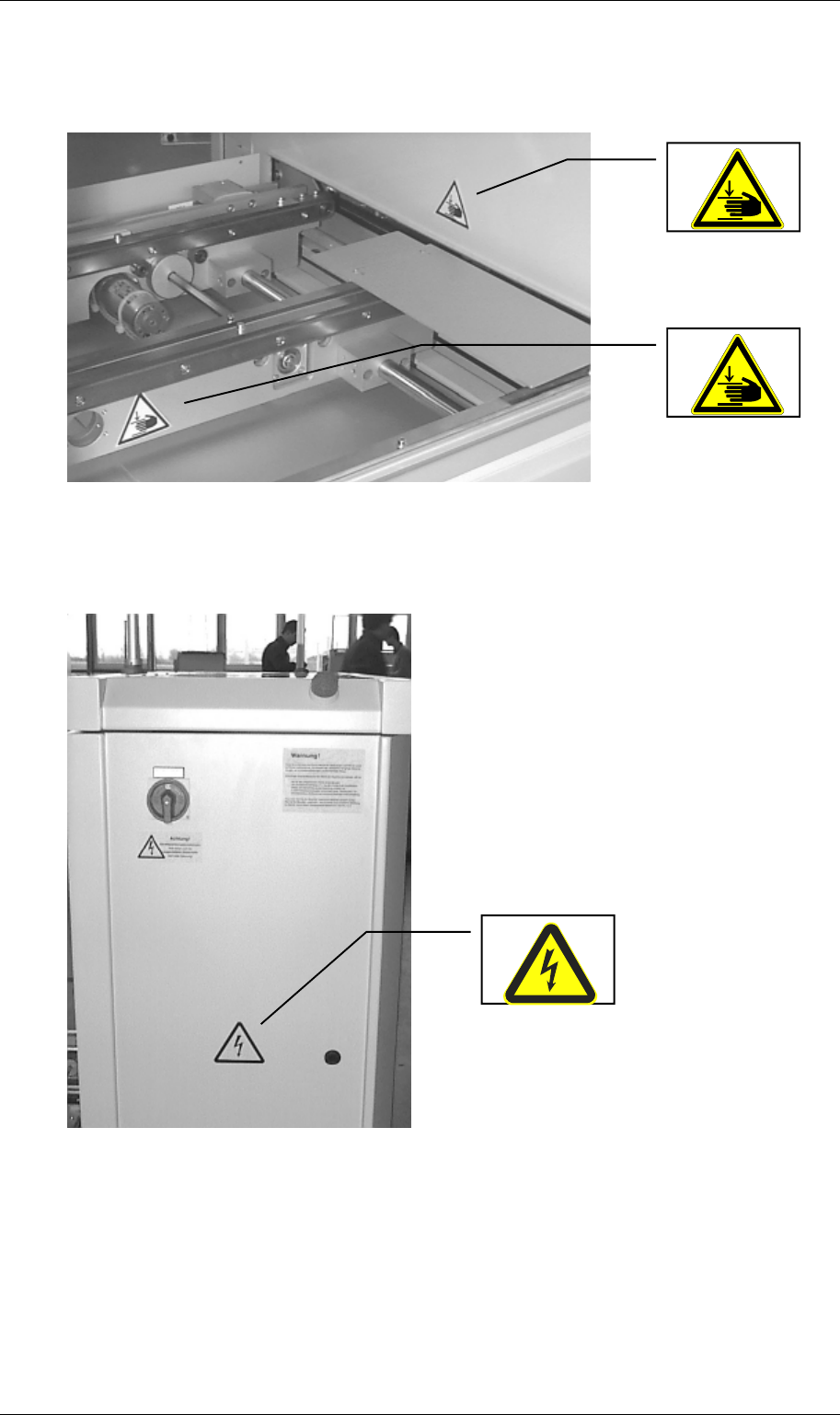
Order No. 00192 169-01 User Manual - Productivity Lift E_SPLFS03_V40_11_0300_200300_V1_14.doc Last update: 20.03.2000 - Version V 1.14 Page 23 Figure 18: Labelling danger underfloor conveyor inlet left 3.6.2.4 Control …
Order No. 00192 169-01 User Manual - Productivity Lift
E_SPLFS03_V40_11_0300_200300_V1_14.doc Last update: 20.03.2000 - Version V 1.14 Page 22
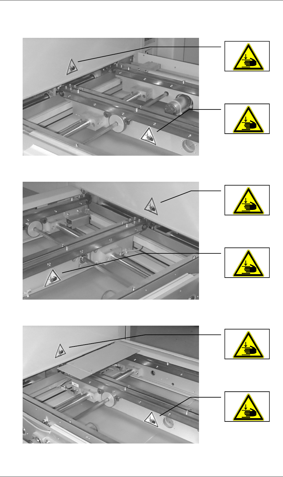
3.6.2.3 Underfloor conveyor
Figure 15: Labelling danger underfloor conveyor outlet left
Figure 16: Labelling danger underfloor conveyor outlet right
Figure 17: Labelling danger underfloor conveyor inlet right
Order No. 00192 169-01 User Manual - Productivity Lift
E_SPLFS03_V40_11_0300_200300_V1_14.doc Last update: 20.03.2000 - Version V 1.14 Page 23
Figure 18: Labelling danger underfloor conveyor inlet left
3.6.2.4 Control cabinet
Figure 19: Labelling danger on the exterior of the control cabinet
Order No. 00192 169-01 User Manual - Productivity Lift
E_SPLFS03_V40_11_0300_200300_V1_14.doc Last update: 20.03.2000 - Version V 1.14 Page 24
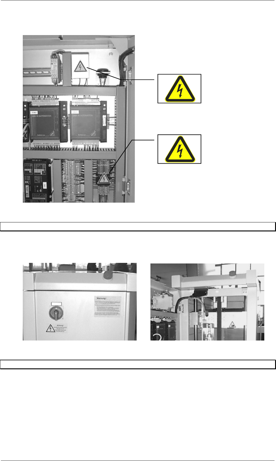
Figure 20: Labelling danger on the interior of the control cabinet
3.7 Emergency stopping switches
There are two emergency stopping switches on each lift module. One is located on the side of
the control desk and the other on the rear side of the lift.
Figure 21: Position of the emergency stopping switches
3.8 Indicator lamps
The device is equipped with one green and one white indicator lamp. The lamps have the
following functions assigned to them:
Green - illuminated: system in automatic operating mode.
White - illuminated : system fault.