00192169-01.pdf - 第25页
Order No. 00192 169-01 User Manual - Productivity Lift E_SPLFS03_V40_11_0300_200300_V1_14.doc Last update: 20.03.2000 - Version V 1.14 Page 25 4 Assembling and installing the device WARNING Work on a system that is not (…
Order No. 00192 169-01 User Manual - Productivity Lift
E_SPLFS03_V40_11_0300_200300_V1_14.doc Last update: 20.03.2000 - Version V 1.14 Page 24
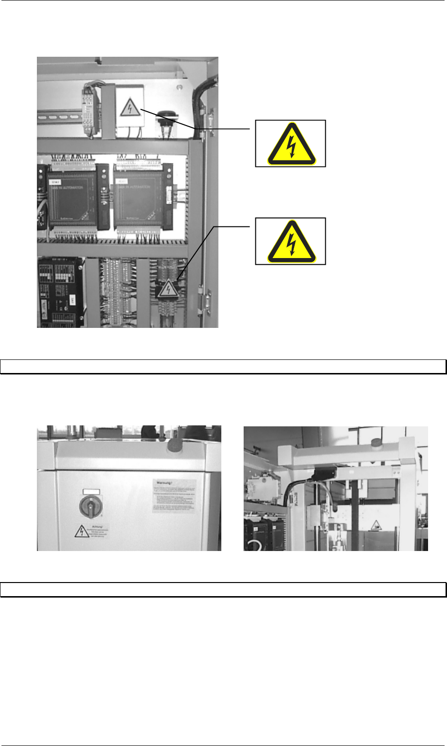
Figure 20: Labelling danger on the interior of the control cabinet
3.7 Emergency stopping switches
There are two emergency stopping switches on each lift module. One is located on the side of
the control desk and the other on the rear side of the lift.
Figure 21: Position of the emergency stopping switches
3.8 Indicator lamps
The device is equipped with one green and one white indicator lamp. The lamps have the
following functions assigned to them:
Green - illuminated: system in automatic operating mode.
White - illuminated : system fault.

Order No. 00192 169-01 User Manual - Productivity Lift
E_SPLFS03_V40_11_0300_200300_V1_14.doc Last update: 20.03.2000 - Version V 1.14 Page 25
4 Assembling and installing the device
WARNING
Work on a system that is not (yet) properly service engineers from the manufacturing company
may only carry out set up.
The device is mounted on feet. These serve both to align the transport height and keep the
device level. The device must be set up in such a way that a printed circuit board can be
accepted (or delivered) by the current system (or a subsequent one) smoothly.
It is helpful to use two of the longest and widest printed circuit boards.
Set the widths of the adjacent devices exactly to the width of the PCB. Then lay one PCB on
the adjacent transport sections. Now the misalignment and the horizontal orientation can be
determined. Make any necessary adjustments.
N.B.
When installing the equipment, the power cord of each lift needs to be labelled with a visible
unit identification label. In case of removal or reconfiguration the label needs to be renewed
according to the new line set-up..
Connect the electrical and any pneumatic supply and install the interface cable.
When connecting the individual components (lower belt modules), the devices must
have been turned off at the main switch beforehand.
Note
⇒ The system must always be in stand-by mode for any adjustments (system on).
⇒ When adjusting the height of the feet, ensure that the transport sections do not collide (due
to the tilting motion of any forwards / backwards movement of the device).
⇒ Once all the settings have been defined, the jam nuts should be screwed down tightly on
the feet.
4.1 Power supply 230V / 50 Hz or 110V / 60 Hz
The machines can be operated using two different power supplies. By changing the wiring of
the power supply PSU 500L24 the appropriate power setting can be adjusted. Please refer to
Appendix D Power unit PSU on page 75.
4.2 Installation and operation instructions
For the installation and operation of the productivity lift the following advisees have to be
observed:
1. Area load allowed for undercover 0,2 t/m²
2. room temperature 15°C until 35°C
3. humidity in the area 30% until 70%
4. average humidity ≥ 45%

Order No. 00192 169-01 User Manual - Productivity Lift
E_SPLFS03_V40_11_0300_200300_V1_14.doc Last update: 20.03.2000 - Version V 1.14 Page 26
4.3 Switching the device on
Once the device has been switched on at the main switch, an emergency stop message
appears in the display, which must be confirmed using the Enter key. This will set the device
to the stand-by-operating mode.
Pressing the Start key sets the device to the automatic operating mode, which begins by
running an initialisation phase. This serves to test basic system functions.
Following this brief initialisation, the device is set to the automatic operating mode and is ready
to operate.
4.4 Installation / Deinstallation of emergency conveyor
The emergency conveyor is used, when the shuttle is not in use e.g. for reasons of
maintenance.
4.4.1 In order to activate the emergency conveyor do the following:
1. By pushing the stop cursor the corresponding conveyor is put into stand-by modus.
2. Through Alt cursor the adjustment modus comes up.
3. Through the Enter cursor the menu comes up on the display which shows PCB
takeover comes up and you can check if the adjustment is dual lane. If this is not the
case one can switch to dual lane as described in the chapter 7.3.
4. Use the enter cursor. The menu PCB transfer comes up. Here it is the same procedure
as described in point 3 (see chapter 7.6).
5. Another use of the enter cursor brings up the menu PCB pass-through. In this menu
the emergency conveyor can be switched on by choosing the adjustment switched on
(see chapter 7.7). This change can be taken over with the enter cursor.
6. The adjustment modus can be quit with the stop cursor.
If the machine is started now the lift conveyor drives down and the emergency conveyor
lowers to the operating position and starts itself. Afterwards the device is again in operation
modus.