00192169-01.pdf - 第45页
Order No. 00192 169-01 User Manual - Productivity Lift E_SPLFS03_V40_11_0300_200300_V1_14.doc Last update: 20.03.2000 - Version V 1.14 Page 45 7.3.3 Ramp down mode PCB distribution parameter, which defines the unloading …
Order No. 00192 169-01 User Manual - Productivity Lift
E_SPLFS03_V40_11_0300_200300_V1_14.doc Last update: 20.03.2000 - Version V 1.14 Page 44
7.3 Ramp up mode / Ramp down mode
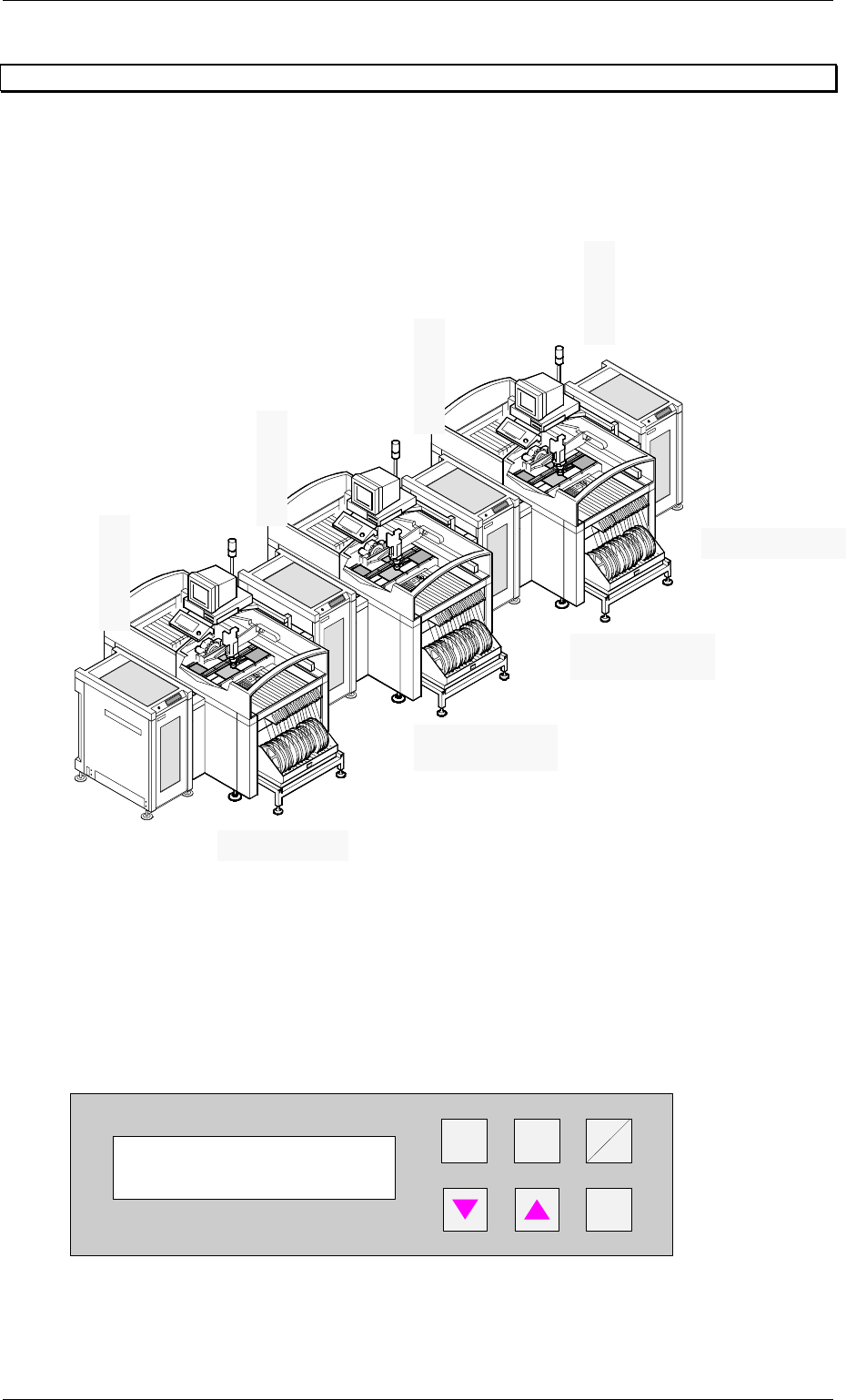
7.3.1 Example of Cluster with three Siplace units
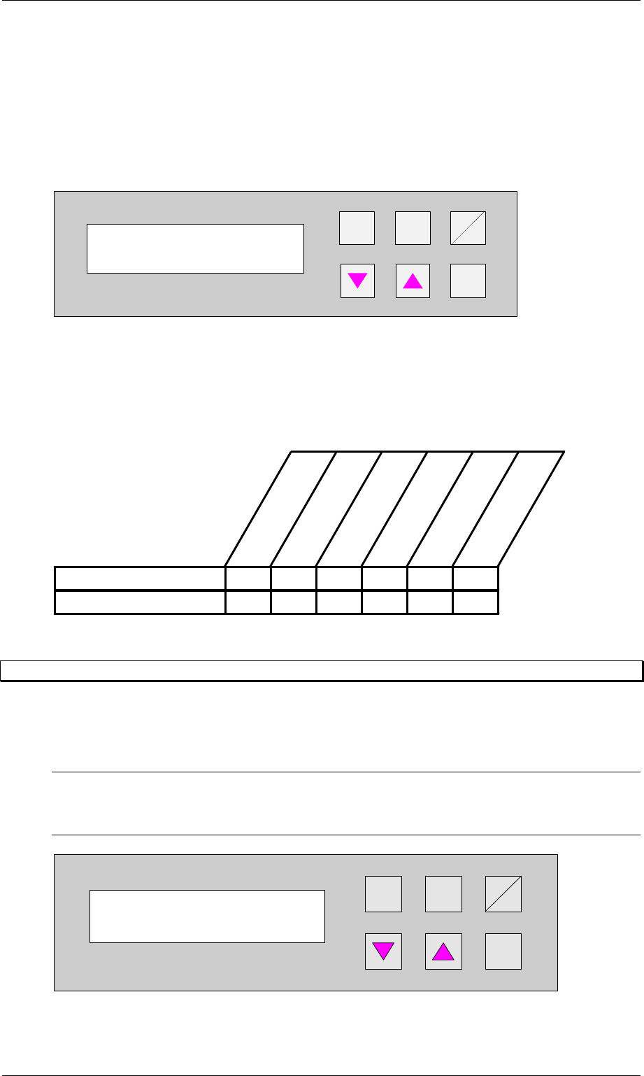
7.3.2 Ramp up mode
PCB distribution parameter, which defines the loading sequence of the PCBs within a cluster
of Siplace units. The value of x depends on the number of Siplace units within a cluster (see
example 7.3.1).
The menu allows to set the value x between 0...9 .
+
Enter
Alt
Stop
Start
Figure 54: Ramp up mode
Ramp up mode
1 to x
Input module
Ramp up mode 1:1
Ramp down mode 1:0
Ramp down mode 1:2
Ramp up mode 1:0
Ramp down mode 1:1
Cluster module
Output module
Cluster module
Ramp up mode 1:2
Order No. 00192 169-01 User Manual - Productivity Lift
E_SPLFS03_V40_11_0300_200300_V1_14.doc Last update: 20.03.2000 - Version V 1.14 Page 45
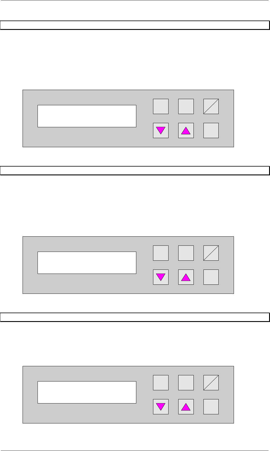
7.3.3 Ramp down mode
PCB distribution parameter, which defines the unloading of the PCBs within a cluster of
Siplace units. The value of x depends on the number of Siplace units within a cluster (see
example 7.3.1).
The menu allows to set the value x between 0...9 .
+
Enter
Alt
Stop
Start
Figure 55: Ramp down mode
7.3.4 Availability of Ramp up / Ramp down mode depending on machine type
The ramp up, ramp down mode depends on the selected machine type as defined in the table
below.
Input module
Cluster module
Cross module
Convert 2/4
Convert 4/2
Output module
Ramp up module XXXX
Ramp down module X X X X
7.4 Underneath buffer
The lower belts can be used as so-called underfloor buffers. This means that if the function is
switched on, two PCBs could be transferred on the belt. As a result, there is an additional
further storage space available for each belt.
N.B.
This menu is not displayed if the underfloor conveyor is switched off (see 6.8 Underneath
belt).
Hand
Stop
Start
Enter
Alt
Figure 56: Underneath buffer
Ramp down mode
1 to x
Underneath buffer
Turned off
Order No. 00192 169-01 User Manual - Productivity Lift
E_SPLFS03_V40_11_0300_200300_V1_14.doc Last update: 20.03.2000 - Version V 1.14 Page 46
7.5 PCB takeover
The possibility of defining the setting for PCB takeover at the inlet of the upper transport level.
The following settings are possible:
Double track: Depending on the request signals, PCBs are taken at the inlet alternately from
track 1 and track 2
Track 1 : PCBs are taken from track 1 only.
Track 2 : PCBs are taken from track 2 only.
Hand
Stop
Start
Enter
Alt
Figure 57: PCB takeover
7.6 PCB handover
The possibility of defining the setting for PCB handover at the outlet of the upper transport
level. The following settings are possible:
Double track: Depending on the request signals, PCBs are taken at the inlet alternately from
track 1 and track 2
Track 1 : PCBs are taken from track 1 only.
Track 2 : PCBs are taken from track 2 only.
Hand
Stop
Start
Enter
Alt
Figure 58: PCB handover
7.7 Pass through
If this function is turned on, PCBs are only taken at the upper inlet track 1 or 2 and only
delivered again at the corresponding upper outlet. This is implemented by the additional top
conveyor module, which is lowered pneumatically to the transport level. This also serves to
turn off the shuttle.
Hand
Stop
Start
Enter
Alt
Figure 59: PCB pass through
PCB takeover
Double track
PCB handover
Double track
PCB pass through
Turned off