00192169-01.pdf - 第48页
Order No. 00192 169-01 User Manual - Productivity Lift E_SPLFS03_V40_11_0300_200300_V1_14.doc Last update: 20.03.2000 - Version V 1.14 Page 48 7.10 PCB inspection 2 This feature allows to inspect a PCB on the transport m…
Order No. 00192 169-01 User Manual - Productivity Lift
E_SPLFS03_V40_11_0300_200300_V1_14.doc Last update: 20.03.2000 - Version V 1.14 Page 47
7.8 Width board
This menu item is only active if the settings automatic or only at start were selected in the
chapter Lead adjusting.
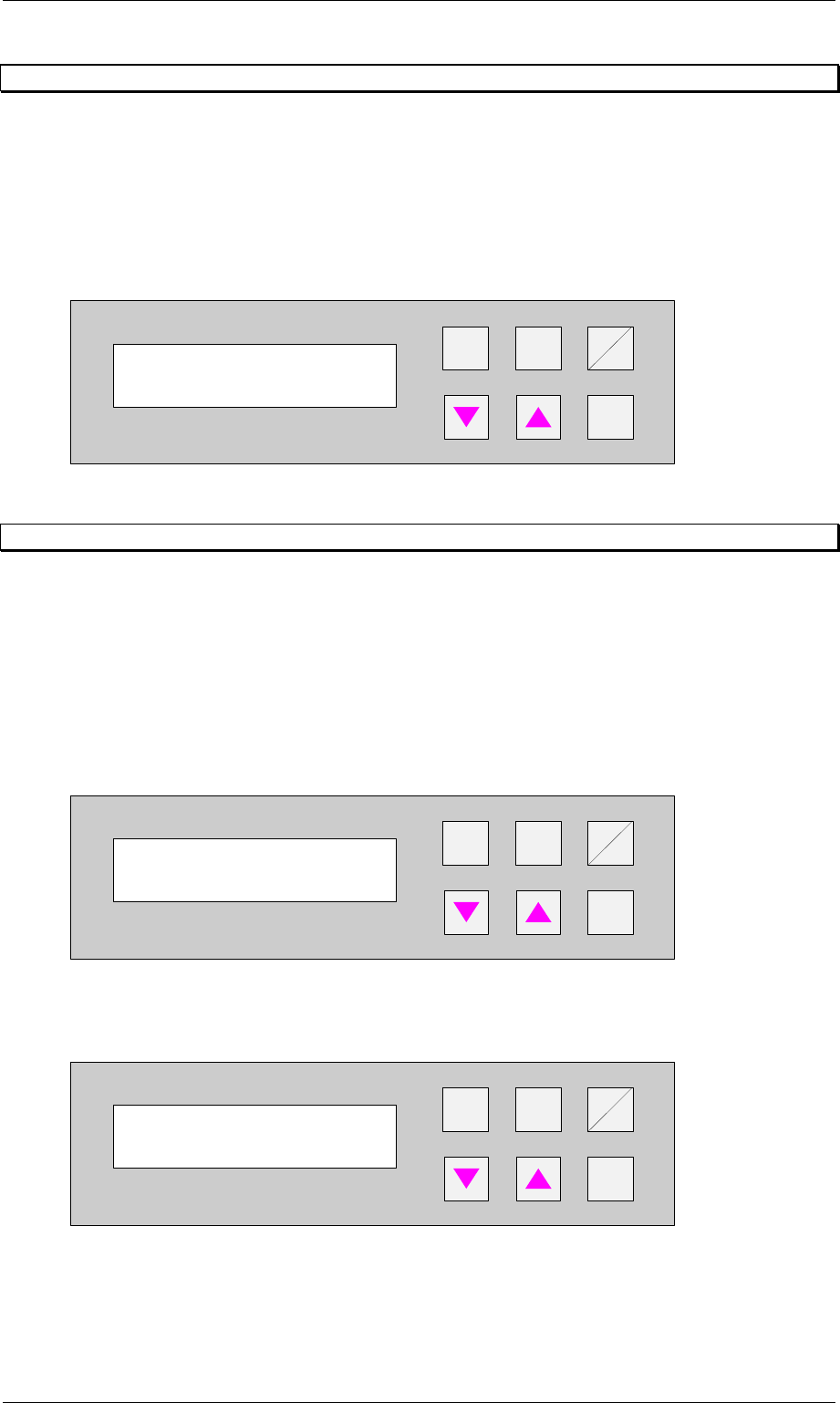
The value to be entered here can be used to prescribe the transport width of the system
numerically as an absolute value. After starting the automatic operating mode, and after each
width adjustment reference run, the width prescribed here is automatically reset.
The unit of value is [0.1 mm] in a setting range of 500 to 2170 (corresponds to 50 mm to 217
mm).
+
Enter
Alt
Stop
Start
Figure 60: Width board
7.9 PCB inspection 1
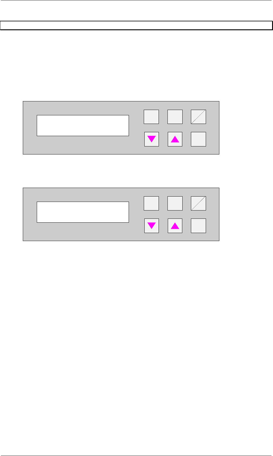
This feature allows to inspect a PCB on the transport modul placed before the Productivity Lift.
This feature can be enabled for an input or cluster module.
The PCB inspection 1 will be conducted on track 1. The entered value defines the control
cycle. The value can be set between 0-99.
Value 0: Function disabled
Value 1: Each PCP is stopped
Value 3: Every third PCB is stopped.
+
Enter
Alt
Stop
Start
Figure 61: PCB inspection 1
If the feature is enabled, the display shows inspection track 1.
+
Enter
Alt
Stop
Start
Figure 62: Inspection track 1
Width board
2000
PCB inspection 1
0 ... 99
Unit runs
Inspection track 1
Order No. 00192 169-01 User Manual - Productivity Lift
E_SPLFS03_V40_11_0300_200300_V1_14.doc Last update: 20.03.2000 - Version V 1.14 Page 48
7.10 PCB inspection 2
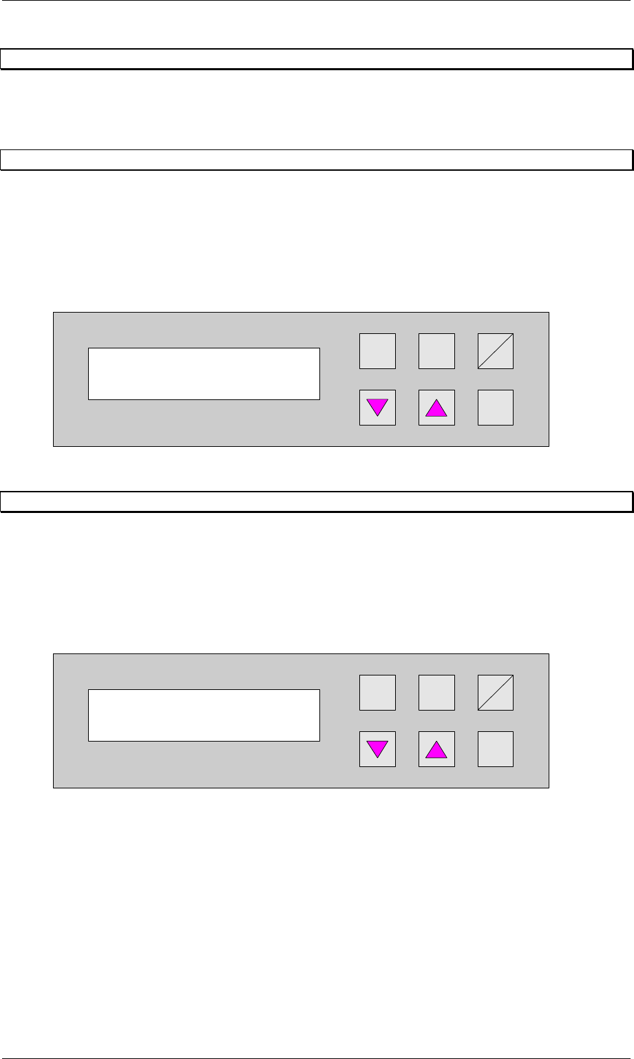
This feature allows to inspect a PCB on the transport modul placed before the Productivity Lift.
This feature can be enabled for a input or cluster module.
The PCB inspection 2 will be conducted on track 2. The entered value defines the control
cycle. The value can be set between 0-99.
Value 0: Function disabled
Value 1: Each PCP is stopped
Value 3: Every third PCB is stopped.
+
Enter
Alt
Stop
Start
Figure 63: PCB inspection 2
If the feature is enabled, the display shows inspection track 2.
+
Enter
Alt
Stop
Start
Figure 64: Inspection track 2
PCB inspection 2
0 ... 99
Unit runs
Inspection track 2
Order No. 00192 169-01 User Manual - Productivity Lift
E_SPLFS03_V40_11_0300_200300_V1_14.doc Last update: 20.03.2000 - Version V 1.14 Page 49
8 Manual mode
In the manual mode, the individual functions can be tested with the aid of the cursor keys.
The Hand key is used for changeover in the manual mode.
8.1 Manual mode 1 Lift 1
Test function for the top conveyor.
The cursor keys s and t can be used to move the top conveyor upwards and downwards,
while the Alt key can be used to switch the belt drive on for as long as the key is pressed
down. The conveyor can only be moved downwards if the shuttle is in its lower position.
The Enter key can be used to proceed to the next test function. To cancel the procedure, exit
the menu using the Start/Stop key.
Hand
Stop
Start
Enter
Alt
Figure 65: Manual mode 1 Lift 1
8.2 Manual mode 2 Lift 2
Test function for the shuttle.
The cursor keys s and t can be used to move the shuttle upwards and downwards, while
the Alt key can be used to switch the belt drive on for as long as the key is pressed down.
The shuttle can only be moved upwards if top conveyor is in its upper position.
The Enter key can be used to proceed to the next test function. To cancel the procedure, exit
the menu using the Start/Stop key.
Hand
Stop
Start
Enter
Alt
Figure 66: Manual mode 2 Lift 2
Manual mode 1
Lift 1
Manual mode 2
Lift 2