00192169-01.pdf - 第56页
Order No. 00192 169-01 User Manual - Productivity Lift E_SPLFS03_V40_11_0300_200300_V1_14.doc Last update: 20.03.2000 - Version V 1.14 Page 56 12 Deinstallation, dismantling, disposal This chapter explains how to deinsta…
Order No. 00192 169-01 User Manual - Productivity Lift
E_SPLFS03_V40_11_0300_200300_V1_14.doc Last update: 20.03.2000 - Version V 1.14 Page 55
11.2 SIEMENS interface definition
When the machine is equipped with interface as the Siemens Definition describes, a 37-pin
AMP plug and socket are used for the connection.
At the inlet:
Pin 28 24V from machine n-1
Pin 29 Interference loop outlet to machine n-1
Pin 30 Own earth connection
Pin 31 Arrived - signal outlet for machine n-1
Pin 32 Ready - signal outlet for machine n-1
Pin 35 Handed over - signal inlet
Pin 36 Demand - signal inlet
Pin 37 Earth connection from machine n-1
At the outlet:
Pin 28 24V from machine n+1
Pin 29 Interference loop outlet to machine n+1
Pin 30 Earth connection of the next machine
Pin 31 Arrived - signal inlet
Pin 32 Ready - signal inlet
Pin 35 Handed over - signal outlet for machine n+1
Pin 36 Demand - sig nal outlet for machine n+1
Pin 37 Own earth connection
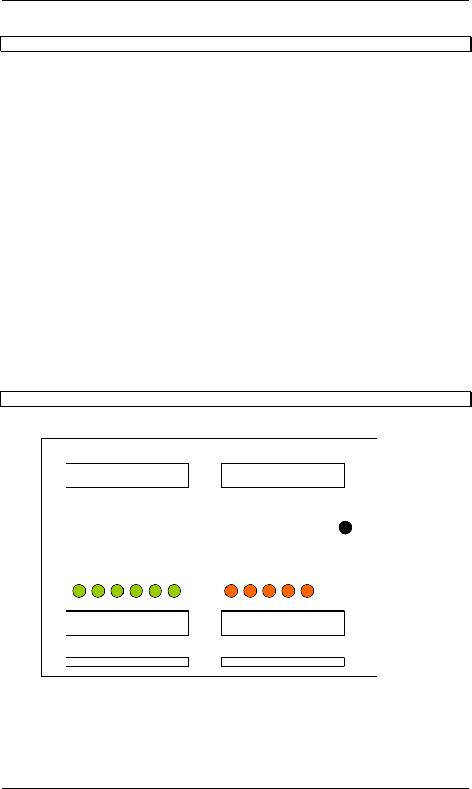
11.3 Interface module
Figure 73: Interface modul AMI 2-x
LEDs Out
p
ut
g
reen
LEDs Inlet 0r.
SS1 Arrived
SS1 Read
y
SS2 Handed
SS2 Demand
SS1 Interference
SS2 Arrived
SS2 Read
y
SS1 Handed
SS1 Demand
SS1 SM1
SS2 SM2
DC 24V
Order No. 00192 169-01 User Manual - Productivity Lift
E_SPLFS03_V40_11_0300_200300_V1_14.doc Last update: 20.03.2000 - Version V 1.14 Page 56
12 Deinstallation, dismantling, disposal
This chapter explains how to deinstall the device. A qualified person or employee (service
engineer) may only do this.
Note
For deninstallation, dismatling or disposal the Productivity Lift has to be prepared. For
installation please refer to Installation instruction (Article No.: 00191 967-01).
12.1 Deinstallation
If the Productivity Lift needs to be removed or moved within a production line, please follow
the instructions below.
1. Position the Top Conveyor in its upper position using the manual mode.
2. Install transport locks (see chapter 3.5).
3. Position Shuttle Conveyor in its lower position.
4. Mount shaft clamp (Figure 3, page 15) to secure Shuttle Conveyor.
5. Press the button marked Stop on the system control panel.
6. Set the main switch to the 0 position.
7. Disconnect the power supply via the main cable and pack it into the control cabinet.
8. Disconnect any pneumatic energy supply by removing the feed hose. Pack it
sensibly into the system.
9. Remove any transport goods and magazines intended for this purpose from the
device.
10. Remove the keys for the key switch located in the control cabinet to bridge the
safety switches of covers and doors.
11. Close and lock all doors and covers.
12.2 Dismantling
Pack and transport the unit after disconnecting, power cords, interface cables and
compressed air lines . Please follow the relevant Safety and Transport regulations during this
process.

Order No. 00192 169-01 User Manual - Productivity Lift
E_SPLFS03_V40_11_0300_200300_V1_14.doc Last update: 20.03.2000 - Version V 1.14 Page 57
12.3 Disposal
Only operators have responsibility for disposal. They must ensure that the system and its
operating supplies are disposed of correctly.
The construction of the system only involved materials that can be easily recycled or are not
harmful when destroyed. Dangerous substances are not necessary for either the construction
or operation of the device.
The relevant national legal provisions must be complied with when disposing of the different
device parts.
12.3.1 Disposing of the device
Dispose of the device by taking it apart, sorting the parts separately according to material, and
disposing of them accordingly.
The device consists of the following materials:
• Frame : steel
• Panelling : steel and plastic
• Mechanical components : aluminium
• Controller : plastics, non-ferrous metals and electronic components