00192169-01.pdf - 第7页
Order No. 00192 169-01 User Manual - Productivity Lift E_SPLFS03_V40_11_0300_200300_V1_14.doc Last update: 20.03.2000 - Version V 1.14 Page 7 2 Operating instructions The objective of the operating instructions is to pro…

Order No. 00192 169-01 User Manual - Productivity Lift
E_SPLFS03_V40_11_0300_200300_V1_14.doc Last update: 20.03.2000 - Version V 1.14 Page 6
Figure 51: Definition / schematic of the transport tracks .......................................................................41
Figure 52: Ident number......................................................................................................................... 41
Figure 53: Machine type ........................................................................................................................ 43
Figure 54: Ramp up mode ..................................................................................................................... 44
Figure 55: Ramp down mode................................................................................................................. 45
Figure 56: Underneath buffer................................................................................................................. 45
Figure 57: PCB takeover........................................................................................................................ 46
Figure 58: PCB handover ...................................................................................................................... 46
Figure 59: PCB pass through................................................................................................................. 46
Figure 60: Width board ......................................................................................................... ................. 47
Figure 61: PCB inspection 1 .................................................................................................................. 47
Figure 62: Inspection track 1.................................................................................................................. 47
Figure 63: PCB inspection 2 .................................................................................................................. 48
Figure 64: Inspection track 2.................................................................................................................. 48
Figure 65: Manual mode 1 Lift 1 ......................................................................................................... 49
Figure 66: Manual mode 2 Lift 2 ......................................................................................................... 49
Figure 67: Manual mode 3 Shuttle...................................................................................................... 50
Figure 68: Manual mode 4 underneath belt........................................................................................ 50
Figure 69: Manual mode 5 width lift 1................................................................................................. 50
Figure 70: Manual mode 6 width lift 2................................................................................................. 51
Figure 71: Manual mode 7 width belts................................................................................................ 51
Figure 72: Technical Data...................................................................................................................... 52
Figure 73: Interface modul AMI 2-x........................................................................................................ 55
Figure 74: Maintenance unit and hand slide valve ................................................................................59
Figure 75: Pneumatic diagram page 1................................................................................................... 60
Figure 76: Pneumatic diagram page 2................................................................................................... 61
Figure 77: Control cabinet Pos. 1 .......................................................................................................... 62
Figure 78: Cable inlet......................................................................................................... .................... 62
Figure 79: Operating panel .................................................................................................................... 63
Figure 80: Lift axle........................................................................................................... ....................... 64
Figure 81: Top conveyor........................................................................................................................ 66
Figure 82: Shuttle............................................................................................................. ...................... 68
Figure 83: Shuttle - Stepper motor......................................................................................................... 68
Figure 84: Underfloor conveyor for Siplace short (S 20) .................................................................... 70
Figure 85: Underfloor conveyor for Siplace long (HS 50)................................................................... 71
Figure 86: Connection cable Lift Lift and Interface cable SPL ASYS modules ............................... 72
Figure 87: Connection cable Lift Placement system for SMEMA and Siemens ................................. 72
Figure 88: Interface cable for SMEMA and Siemens interfaces............................................................ 72
Figure 89: Fault information LP blocked ................................................................................................ 84
Order No. 00192 169-01 User Manual - Productivity Lift
E_SPLFS03_V40_11_0300_200300_V1_14.doc Last update: 20.03.2000 - Version V 1.14 Page 7
2 Operating instructions
The objective of the operating instructions is to provide the user with an introduction as to how
to make proper and safe use of the device.
For this objective to be achieved, it is imperative that the user studies chapter 3 Safety in
detail and follows these operating instructions.
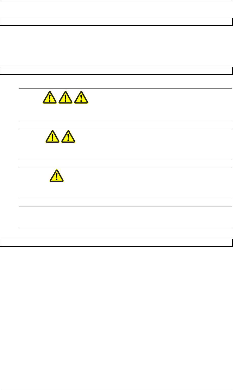
2.1 Definitions
DANGER
Within the context of these instructions, this means that death, serious physical injury or
considerable damage to property will occur if the danger notices are not complied with.
WARNING
Within the context of these instructions, this means that death, serious physical injury or
considerable damage to property can occur if the danger notices are not complied with.
ATTENTION
Within the context of these instructions, this means that slight physical injury or damage to
property can occur if the precautions are not complied with.
N. B.
Within the context of these instructions, this is important information about the product or a
particular part of the instructions that should be consulted in detail.
2.2 Organisational measures
Should you have any questions that are not answered by the operating instructions, please
contact the device manufacturer direct.
2.2.1 Location of the operating instructions
The operating instructions can only be of use if they are available at all times. Therefore
always keep them together with the device.

Order No. 00192 169-01 User Manual - Productivity Lift
E_SPLFS03_V40_11_0300_200300_V1_14.doc Last update: 20.03.2000 - Version V 1.14 Page 8
2.2.2 Manufacturer and contact address
Siemens AG
PL EA 1 V MC
Rupert-Mayer-Str. 44
D-81359 Munich
3 Safety
This chapter contains information on how to make safe and optimum use of the device
described here.
3.1 Overview
This device poses very few risks and is simple and safe for the informed user to operate.
Users who do not possess sufficient knowledge, however, can cause damage to the device by
performing illegal operations. This chapter provides information regarding the requirements for
safe and optimum operation of the device.
All those authorised to operate, maintain and repair the device must read chapter 3 Safety.
3.2 Safety concept
The safety concept controls the authorisation to use the device and the responsibility of the
individual users.
This device has been developed and constructed in accordance with the latest technological
standards and the approved safety regulations. It therefore conforms to EU requirements.
3.2.1 Intended use of the device
The device was designed for its use as prescribed. If it is used for anything other than the
application listed, the manufacturer can not be held responsible for any damage that may
occur as a result.
3.2.1.1 Prescribed use
The prescribed use of the device covers the following:
The Productivity Lift serves to increase the throughput of Siplace automatic placement
machines. Every lift unit has a placement machine of this type. Several lift units arranged in
series thus enable the parallel arrangement of placement machines although these are
physically arranged in a row.
At the inlet of the first lift unit (input module), printed circuit boards can be transferred on two
parallel tracks. They are then delivered to the first subsequent placement machine for
processing. If this placement machine is currently occupied or perhaps even out of service, the
transferred PCBs are forwarded to the next placement machine but one. It is however
necessary that this placement machine is of the same type as the previous one. The type of
placement machine can change within such a line of placement machines by means of the
relevant settings in the device configuration. The final module at the end of such a line hands
the assembled printed circuit boards over to the following production line.