00192169-01.pdf - 第83页
在线预览 00192169-01.pdf PDF 文档。
Order No. 00192 169-01 User Manual - Productivity Lift
E_SPLFS03_V40_11_0300_200300_V1_14.doc Last update: 20.03.2000 - Version V 1.14 Page 59
14 Appendix B Pneumatic diagram
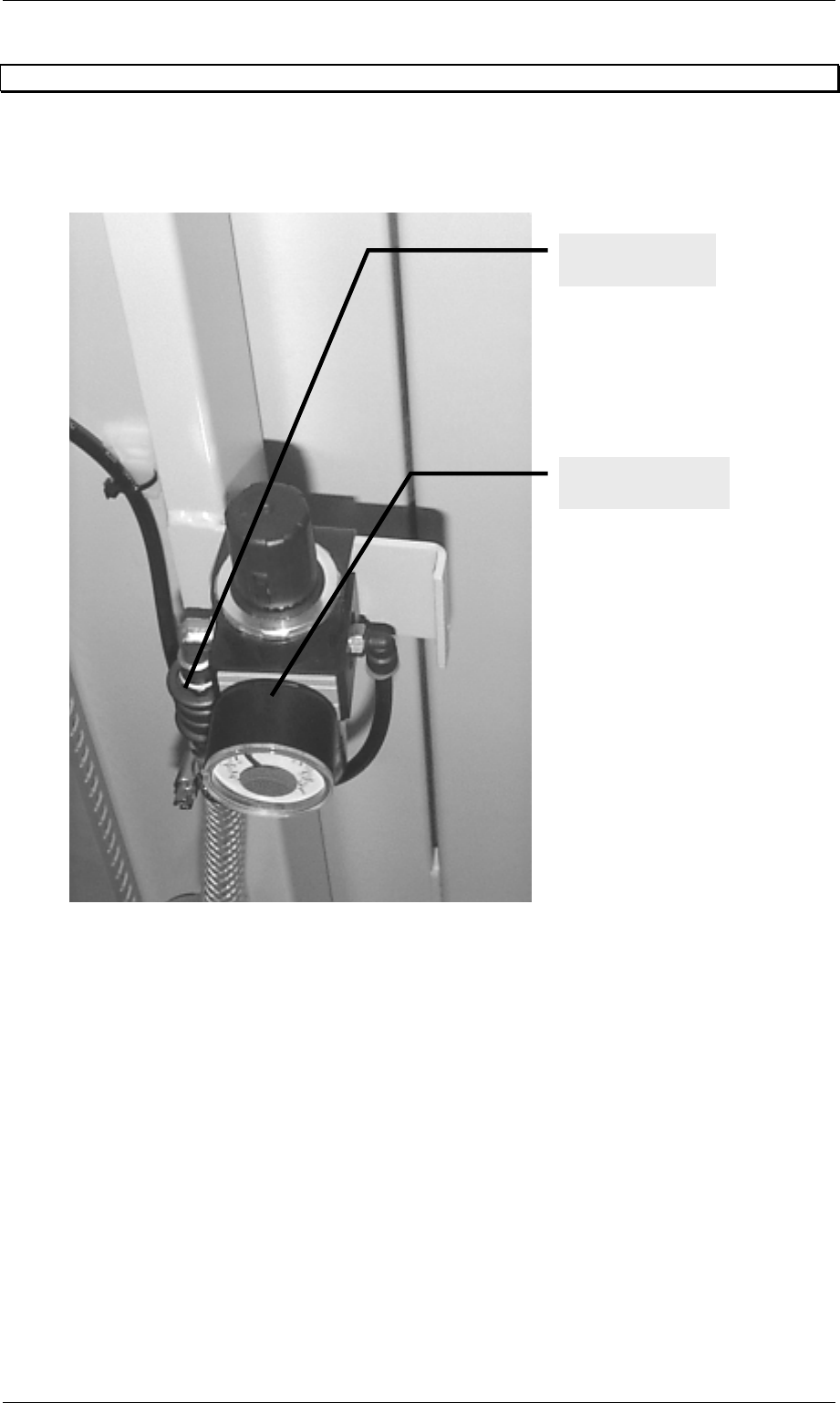
The pneumatic supply can be interrupted by a hand slide valve, which is placed in front of the
maintenance unit. Therefore it is not necessary to change the adjusted pressure (see picture).
Figure 74: Maintenance unit and hand slide valve
Hand slide valve
W-3-1/8
Maintenance unit
with manometer