DFD6361-Maintenance.pdf - 第105页
B-33 Safety pr ecautio ns for mou nting th e hub mo unt (1.2 k W spindle) ( Continued) CAUTION W he n y ou mount a hu b mount to the 1. 2k W spindle, do not insert t he washer between t he loc k bolt and f lang e. Als o,…
B-32
Safety precautions for mounting the hub mount (1.2 kW spindle) (Continued)
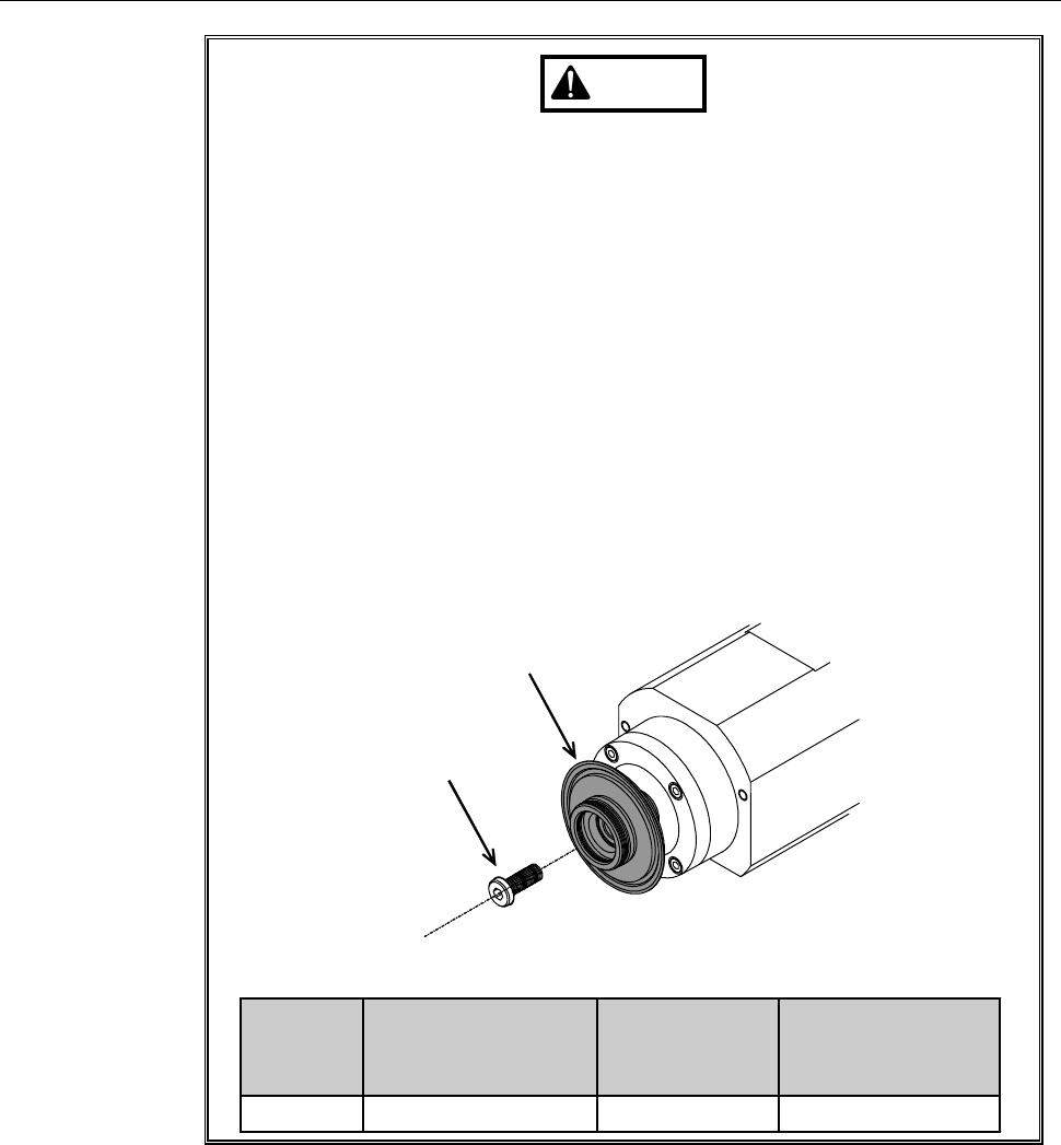
WARNING
- If the lock bolt is tightened to a torque smaller than specified, it may
come off to incur hub mount separation that could cause personal
injury or damage to the machine.
Tighten the lock bolt to the specified torque with the supplied torque
wrench.
[Procedures for tightening the lock bolt]
1: Torque the lock bolt to 4.0 N·m.
2: Close the cover.
3: Turn ON the spindle at the rotating speed to be used for cutting.
(Any button operation including turning OFF the spindle will be
deactivated until the rotating speed reaches the maximum.)
4: After the spindle rotation for sufficient time, turn OFF the spindle.
(Spindle rotations for too short time may cause flange loosing
while cutting. Take due account of the "Time to reach maximum
speed" in the table below.)
5: Torque the lock bolt to 4.0 N·m again.
Hub mount
Lock bolt
Blade
diameter
[inch]
Maximum spindle
rotating speed
[min
-1
(rpm)]
Time to reach
maximum
speed [s]
Time needed for
complete stop [s]
2 60,000 14 15
B-33
Safety precautions for mounting the hub mount (1.2 kW spindle) (Continued)
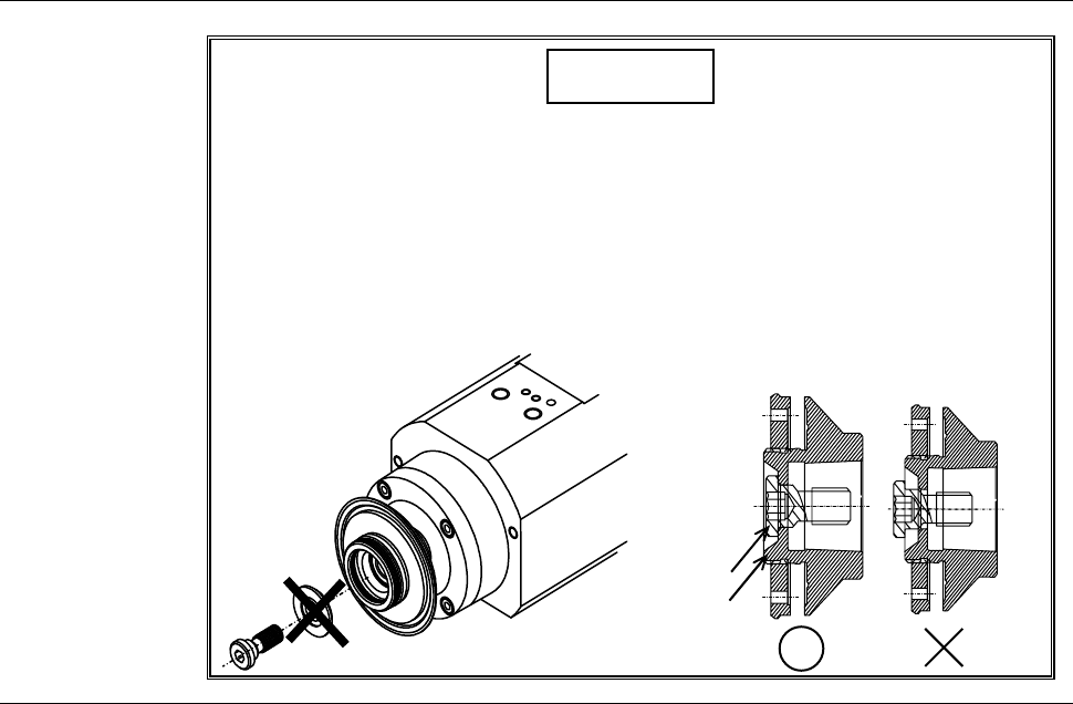
CAUTION
When you mount a hub mount to the 1.2kW spindle, do not insert the
washer between the lock bolt and flange. Also, after mounting the
hub mount, make sure that the bolt does not protrude from the end
face of the hub mount.
If the lock bolt is tightened with the washer and if the bolt protrudes
from the end face of the hub mount, it will causes a collision between
the Y1- and Y2-axis and the spindle may be broken.
End face
Bolt
B-34
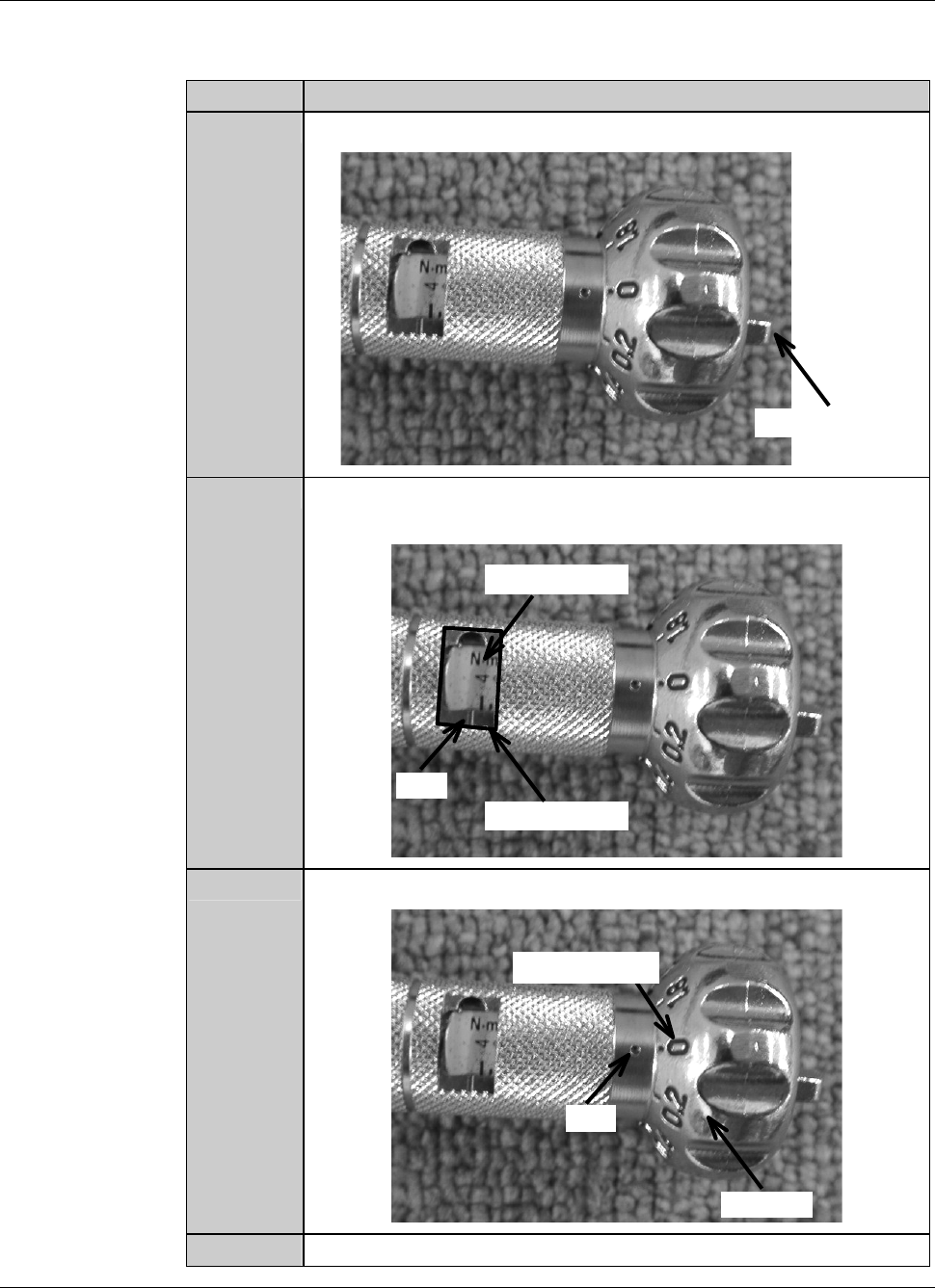
Procedures to adjust the torque of the torque wrench
As an example, the table below shows the procedure to adjust the torque of the
torque wrench to 4.0N
⋅m.
Step No. Do This
1
Loosen the wing bolt at the tail of the torque driver.
Wing bolt
2
Turn the handle to align the calibration of 4 with the mark of the
torque indicator.
Torque indicator
Mark
Calibration
3
Align the dial scale of 0 to the mark of the handle.
Handle
Mark
Dial scale
4
Tighten the wing bolt at the tail of the torque driver.