DFD6361-Maintenance.pdf - 第106页
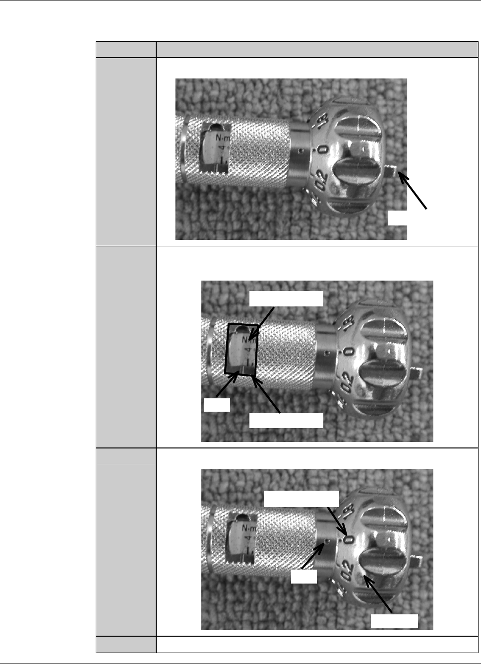
B-34 Procedur es to adjust t he torq ue of the tor que w rench As an example, the table below shows the proc edure to adjust the torque of the torque wrench to 4.0N ⋅ m. St e p N o . Do This 1 Loosen the wing bolt at the…
B-33
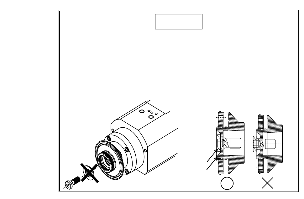
Safety precautions for mounting the hub mount (1.2 kW spindle) (Continued)
CAUTION
When you mount a hub mount to the 1.2kW spindle, do not insert the
washer between the lock bolt and flange. Also, after mounting the
hub mount, make sure that the bolt does not protrude from the end
face of the hub mount.
If the lock bolt is tightened with the washer and if the bolt protrudes
from the end face of the hub mount, it will causes a collision between
the Y1- and Y2-axis and the spindle may be broken.
End face
Bolt
B-34
Procedures to adjust the torque of the torque wrench
As an example, the table below shows the procedure to adjust the torque of the
torque wrench to 4.0N
⋅m.
Step No. Do This
1
Loosen the wing bolt at the tail of the torque driver.
Wing bolt
2
Turn the handle to align the calibration of 4 with the mark of the
torque indicator.
Torque indicator
Mark
Calibration
3
Align the dial scale of 0 to the mark of the handle.
Handle
Mark
Dial scale
4
Tighten the wing bolt at the tail of the torque driver.
B-35
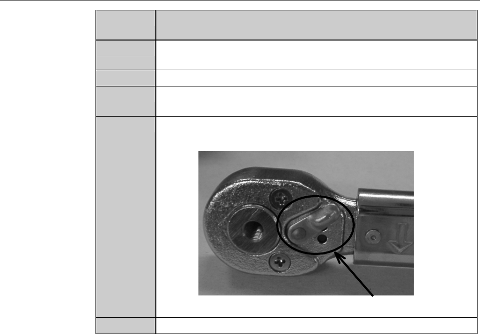
Procedures for mounting the hub mount (1.2 kW spindle)
Step No. Do This
(Continued from the previous section)
1
Clean the hub mount and spindle taper section with lint-free
waste moistened with alcohol, and then blow air to remove water.
2
Fit the hub mount onto the spindle taper section.
3
Adjust the torque of the torque wrench.
Torque for 1.2kW spindle: 4.0 N·m
4
Adjust the direction selector lever so that specified torque will be
produced when you turn the torque wrench clockwise.
Direction selector lever
5
Have on hand the torque wrench set.