DFD6361-Maintenance.pdf - 第107页
B-35 Procedur es for mo unting the hub moun t (1.2 k W spindle) St e p N o . Do This (Continued from the previous section) 1 Clean the hub mount and spindle taper section with lint-free waste moistened with alcohol, and …
B-34
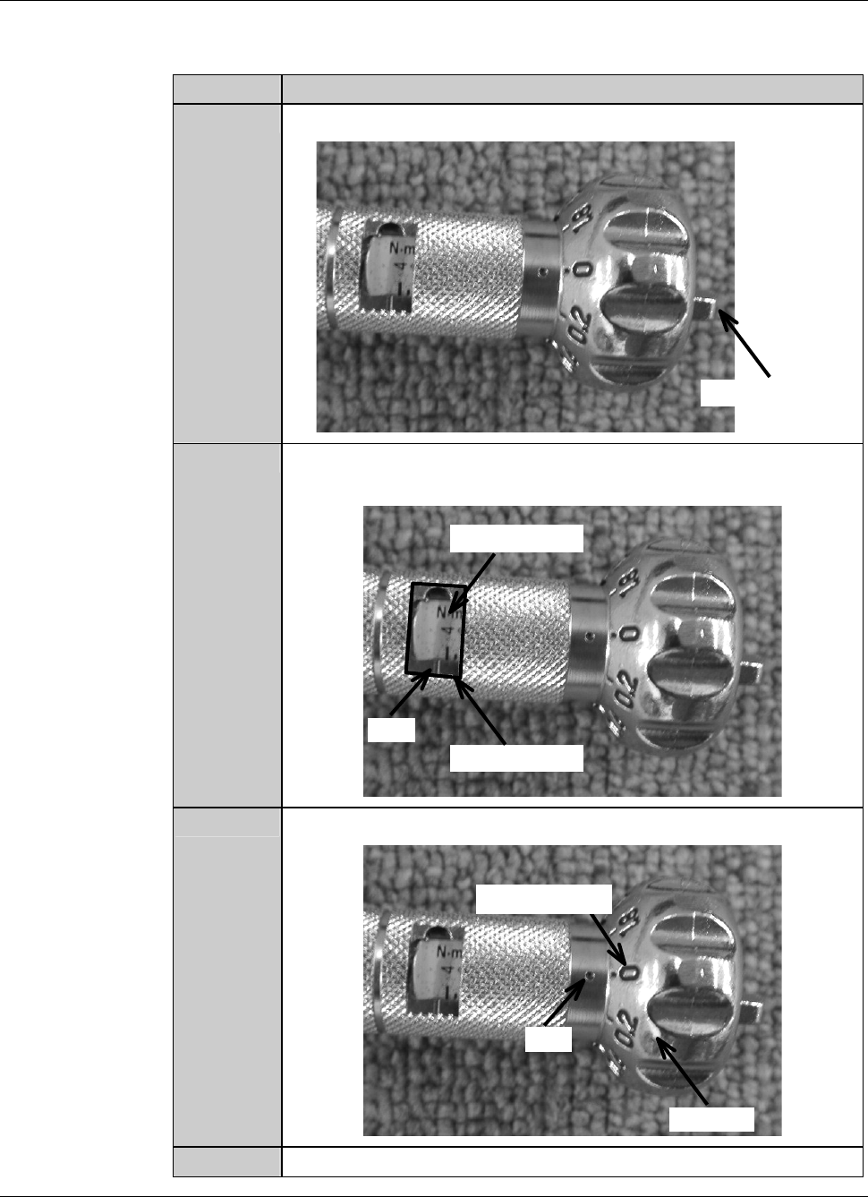
Procedures to adjust the torque of the torque wrench
As an example, the table below shows the procedure to adjust the torque of the
torque wrench to 4.0N
⋅m.
Step No. Do This
1
Loosen the wing bolt at the tail of the torque driver.
Wing bolt
2
Turn the handle to align the calibration of 4 with the mark of the
torque indicator.
Torque indicator
Mark
Calibration
3
Align the dial scale of 0 to the mark of the handle.
Handle
Mark
Dial scale
4
Tighten the wing bolt at the tail of the torque driver.
B-35
Procedures for mounting the hub mount (1.2 kW spindle)
Step No. Do This
(Continued from the previous section)
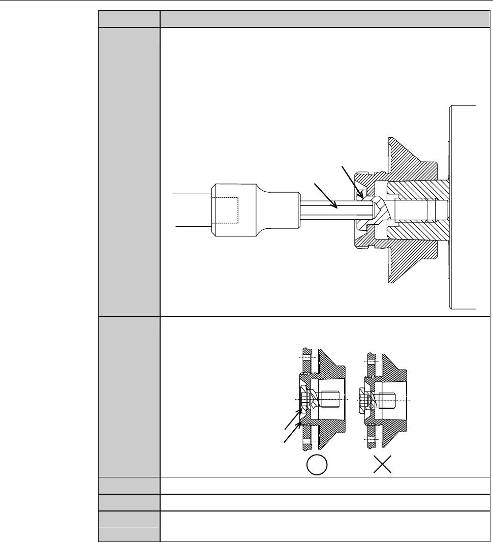
1
Clean the hub mount and spindle taper section with lint-free
waste moistened with alcohol, and then blow air to remove water.
2
Fit the hub mount onto the spindle taper section.
3
Adjust the torque of the torque wrench.
Torque for 1.2kW spindle: 4.0 N·m
4
Adjust the direction selector lever so that specified torque will be
produced when you turn the torque wrench clockwise.
Direction selector lever
5
Have on hand the torque wrench set.
B-36
Procedures for mounting the hub mount (1.2 kW spindle) (Continued)
Step No. Do This
6
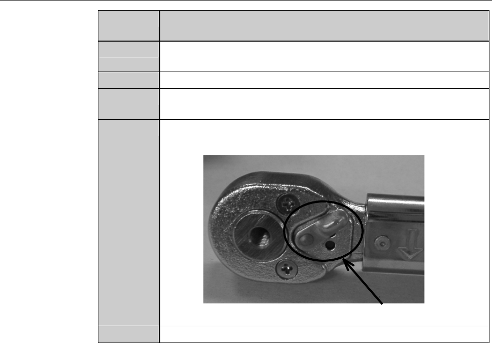
Using the torque wrench set, torque the lock bolt to 4.0 N·m.
- To tighten the bolt, turn the torque wrench clockwise.
- Turn the torque wrench slowly.
- When the torque reaches the specified one, you feel light
resistance.
Lock bolt
Bit
7
Make sure that the bolt does not protrude from the end face of the
hub mount.
End face
Bolt
8
Close the splash cover.
9
Press the <Close> button to release lock of the touch panel.
10
Press the <EXIT> button to call up the MAIN MENU
[screen 0.0].