DFD6361-Maintenance.pdf - 第129页
B-57 Procedur es for re moving the hub moun t (1.8 k W spindle) (Conti nued) St e p N o . Do This 9 T urn the t orque wrench counterclockwise. - The lock bolt rotates co unterclockwise and comes loose. 10 Remove the lock…
B-56
Procedures for removing the hub mount (1.8 kW spindle)
Step No. Do This
1
Call up the BLADE REPLACEMENT screen [screen 4.1].
- The Y-axis moves to its origin position.
2
Make sure that the spindle is OFF.
3
Press the Disco's logo button located at the upper left of the
screen to lock up the touch panel.
4
Open the splash cover.
5
Remove the lock nut for hub and blade.
- For procedures to remove them;
See the section B-6 of Operation Manual, [Blade Maintenance].
6
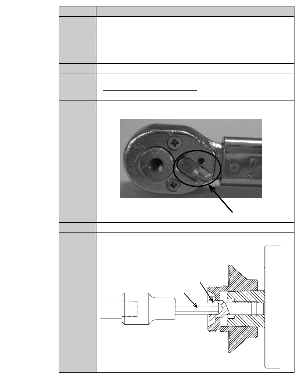
Adjust the direction selector lever so that the wrench does not
turn free when you turn the torque wrench counterclockwise.
Direction selector lever
7
Have on hand the torque wrench set.
8
Insert the bit into the center hole of the lock bolt.
Lock bolt
Bit
B-57
Procedures for removing the hub mount (1.8 kW spindle) (Continued)
Step No. Do This
9
Turn the torque wrench counterclockwise.
- The lock bolt rotates counterclockwise and comes loose.
10
Remove the lock bolt.
11
Insert the pin of the removing jig A into the hole at the center of
the spindle.
12
Screw the removing jigA in the screw thread at the tip of the hub
mount and turn it twice or more.
- In order to screw the removing jigA in the hub mount, turn it
clockwise.
- If the removing jig A is screwed in shallowly, this could lead to
breakage of the hub mount.
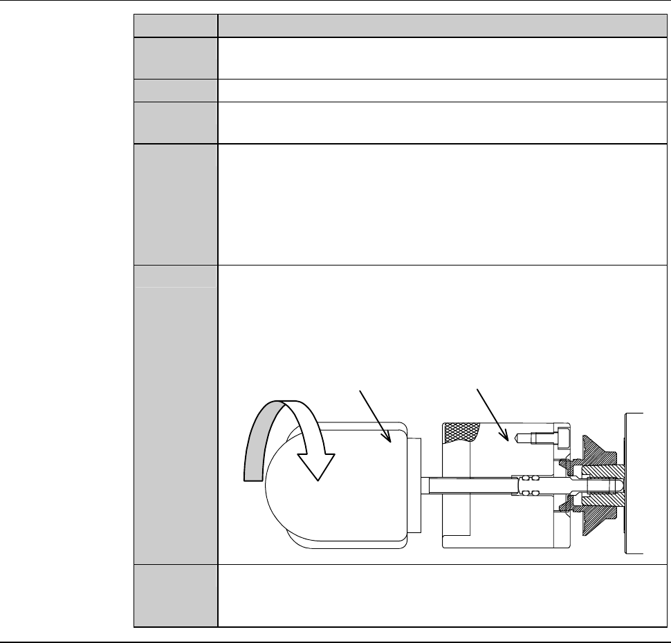
13
While holding the removing jig A so that it does not turn, screw
the removing jig B in the tap hole at the tail of the removing jig
A.
- In order to screw the removing jig B in the jig A, turn it
clockwise.
Removing jig A
Removing jig B
Turn it clockwise
14
While holding the removing jig A so that it does not turn, turn the
removing jig B clockwise.
- The hub mount comes off.
Continued in the next section.
B-58
2-4-2. Mounting the hub mount (1.8 kW spindle)
Safety precautions for mounting the hub mount (1.8 kW spindle)
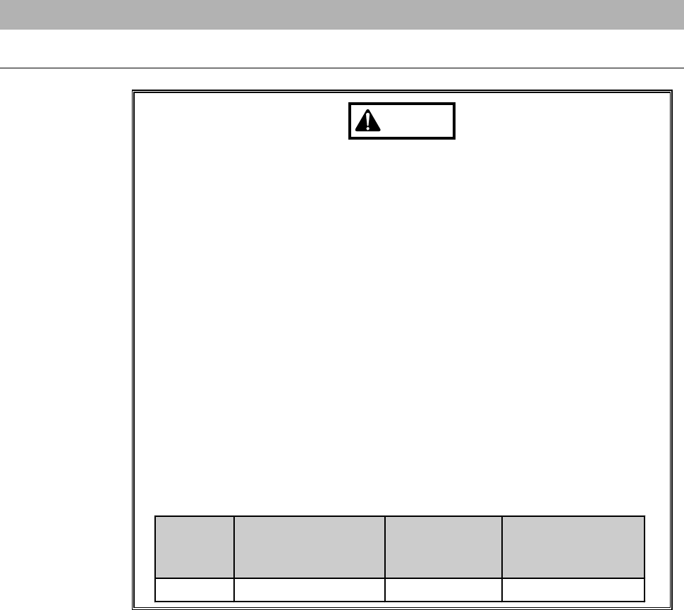
WARNING
- In the hub-mount mounting operation, you have to touch the
spindle-axis section and axis operating section directly by your
hands. Unless the spindle stops, your hands or fingers may be
caught or cut off.
Before opening the splash cover, visually make sure from outside of
the cover that the spindle is completely stopped.
Ensure that no other person touches the machine during operation.
While you don't use the touch panel, press the Disco's logo button
located at the upper left of the screen in order to lock up and
deactivate the touch panel.
- If the spindle is rotated at a speed higher than the maximum
permissible speed for the blade outside diameter, blade breakage
or hub mount separation may occur and cause personal injury or
damage to the machine.
The spindle rotating speed varies depending on the outside
diameter of the installed blade. Be sure that the employed spindle
rotating speed is suitable for the outside diameter of the installed
blade.
Blade
diameter
[inch]
Maximum spindle
rotating speed
[min
-1
(rpm)]
Time to reach
maximum
speed [s]
Time needed for
complete stop [s]
2 60,000 30 15