DFD6361-Maintenance.pdf - 第141页
B-69 Procedur es for re moving the fl ange (2. 2 kW s pindle) St e p N o . Do This 1 Call up t he BLADE REPLACEMEN T screen [screen 4.1]. - The Y -axis moves to its origin position. 2 Make sure that the spindle is OFF . …
B-68
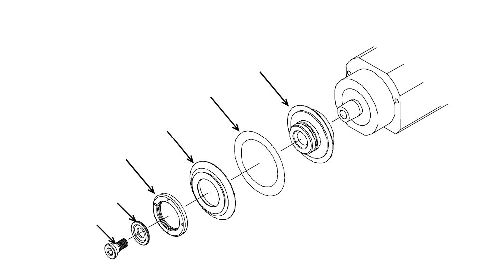
Exploded view of flange and blade (2.2 kW spindle)
The flange and blade are to be mounted as illustrated below.
[2.2 kW spindle: S-type flange]
Flange B
Flange A
Flange B lock nut
Blade
Lock bolt
Washer
B-69
Procedures for removing the flange (2.2 kW spindle)
Step No. Do This
1
Call up the BLADE REPLACEMENT screen [screen 4.1].
- The Y-axis moves to its origin position.
2
Make sure that the spindle is OFF.
3
Press the Disco's logo button located at the upper left of the
screen to lock up the touch panel.
4
Open the splash cover.
5
Remove the flange B lock nut, flange B and blade.
- For procedures to remove them;
See the section B-6 of Operation Manual, [Blade Maintenance].
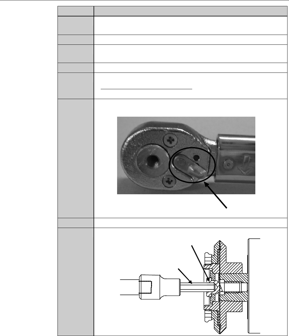
6
Adjust the direction selector lever so that the wrench does not
turn free when you turn the torque wrench counterclockwise.
Direction selector lever
7
Have on hand the torque wrench set.
8
Insert the bit into the center hole of the lock bolt.
Lock bolt
Bit
B-70
Procedures for removing the flange (2.2 kW spindle) (Continued)
Step No. Do This
9
Turn the torque wrench counterclockwise.
- The lock bolt rotates counterclockwise and comes loose.
10
Remove the lock bolt and washer.
11
Insert the pin of the removing jig A into the hole at the center of
the spindle.
12
Screw the removing jig A in the screw thread at the tip of the
flange A and turn it twice or more.
- In order to screw the removing jig A in the flangeA, turn it
clockwise.
- If the removing jig Ais screwed in shallowly, this could lead to
breakage of the flange A.
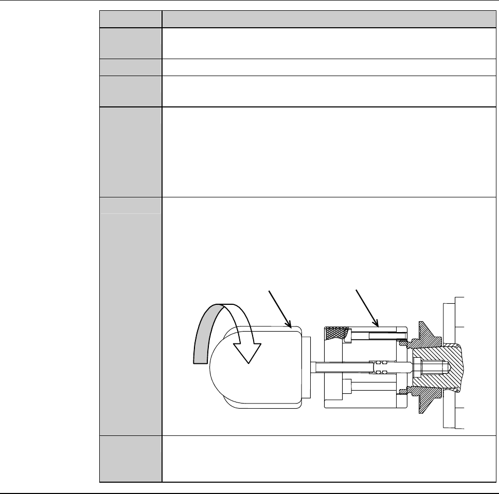
13
While holding the removing jig A so that it does not turn, screw
the removing jig B in the tap hole at the tail of the removing jig
A.
- In order to screw the removing jig B in the jig A, turn it
clockwise.
Removing jig A
Removing jig B
Turn it clockwise
14
While holding the removing jig A so that it does not turn, turn the
removing jig B clockwise.
- The flange A comes off.
Continued in the next section.