DFD6361-Maintenance.pdf - 第146页
B-74 Procedur es to adjust t he torq ue of the tor que w rench As an example, the table below shows t he procedure to adjust the torque of the torque wrench to 8.0 N ⋅ m. St e p N o . Do This 1 Loosen the wing bolt at th…
B-73
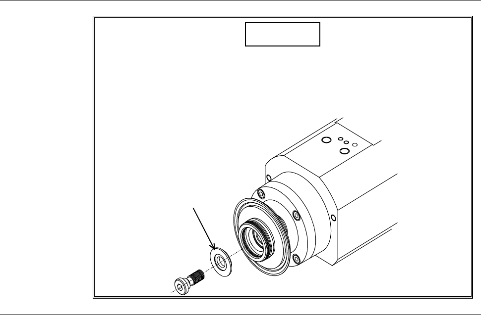
Safety precautions for mounting the flange (2.2 kW spindle) (Continued)
CAUTION
When you mount a flange to the 2.2kW spindle, you should insert the
washer between the lock bolt and flange.
Without the washer, you cannot screw up the lock bolt tight, thus, you
cannot mount the flange.
Washer
B-74
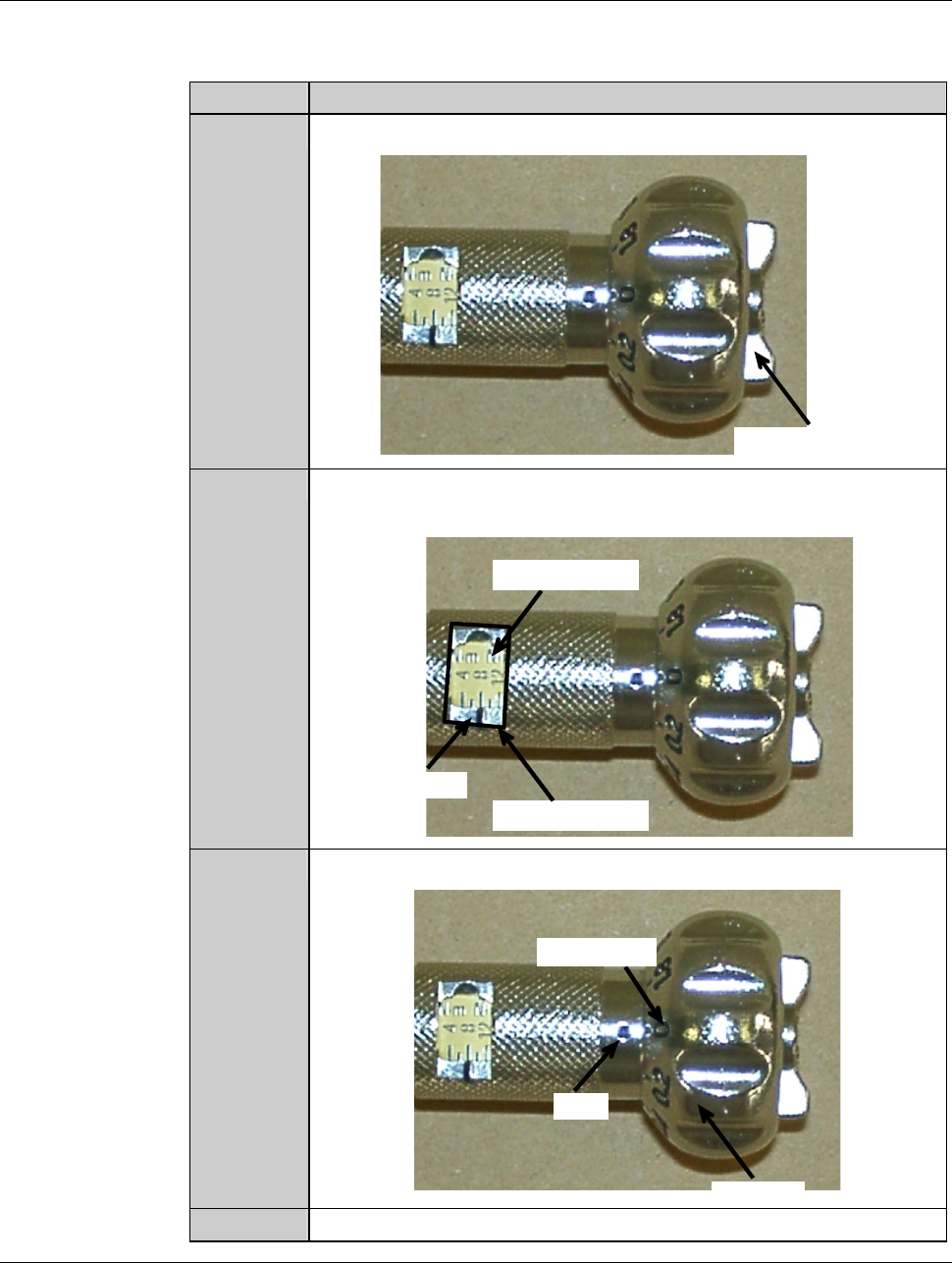
Procedures to adjust the torque of the torque wrench
As an example, the table below shows the procedure to adjust the torque of the
torque wrench to 8.0 N
⋅m.
Step No. Do This
1
Loosen the wing bolt at the tail of the torque driver.
Wing bolt
2
Turn the handle to align the calibration of 8 with the mark of the
torque indicator.
Torque indicator
Mark
Calibration
3
Align the dial scale of 0 to the mark of the handle.
Handle
Mark
Dial scale
4
Tighten the wing bolt at the tail of the torque driver.
B-75
Procedures for mounting the flange (2.2 kW spindle)
Step No. Do This
(Continued from the previous section)
1
Clean the flange A and spindle taper section with lint-free waste
moistened with alcohol, and then blow air to remove water.
2
Fit the flange A onto the spindle taper section.
3
Adjust the torque of the torque wrench.
Torque for 2.2kW spindle: 8.0 N·m
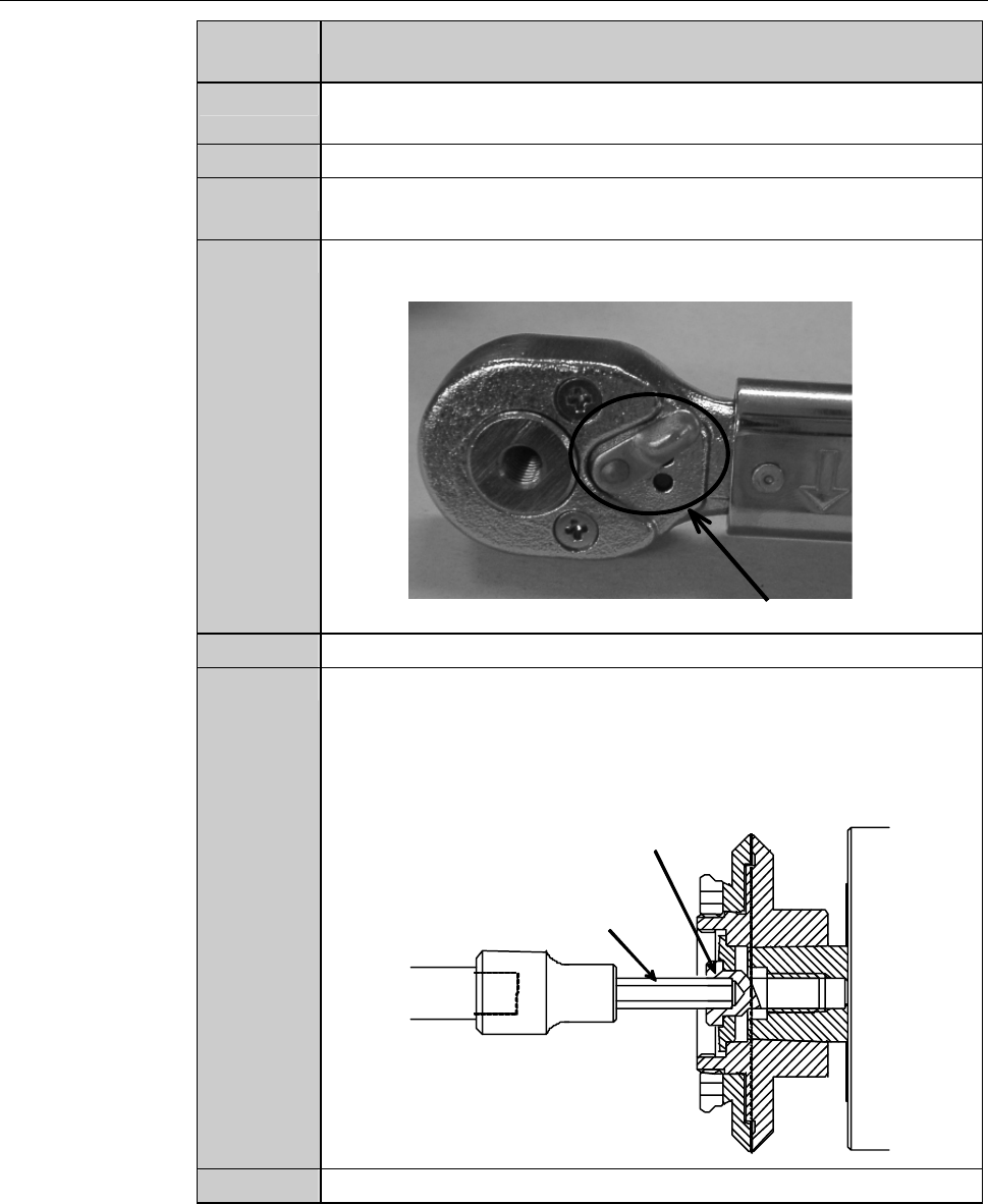
4
Adjust the direction selector lever so that specified torque will be
produced when you turn the torque wrench clockwise.
Direction selector lever
5
Have on hand the torque wrench set.
6
Using the torque wrench set, torque the lock bolt to 8.0 N·m.
- To tighten the bolt, turn the torque wrench clockwise.
- Turn the torque wrench slowly.
- When the torque reaches the specified one, you feel light
resistance.
Lock bolt
Bit
7
Close the splash cover.