DFD6361-Maintenance.pdf - 第156页
B-84 2-6-2. Mou nting the hub mount (2.2 kW spindle) Safety pr ecautio ns for mou nting th e hub mo unt (2.2 k W spindle) W ARNING - In the hub-mo unt m ountin g ope ration, you have to t ouch t he spindle-ax is section …
B-83
Procedures for removing the hub mount (2.2 kW spindle) (Continued)
Step No. Do This
9
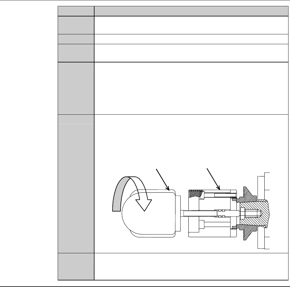
Turn the torque wrench counterclockwise.
- The lock bolt rotates counterclockwise and comes loose.
10
Remove the lock bolt and washer.
11
Insert the pin of the removing jig A into the hole at the center of
the spindle.
12
Screw the removing jig A in the screw thread at the tip of the hub
mount and turn it twice or more.
- In order to screw the removing jig A in the hub mount, turn it
clockwise.
- If the removing jig A is screwed in shallowly, this could lead to
breakage of the hub mount.
13
While holding the removing jig A so that it does not turn, screw
the removing jig B in the tap hole at the tail of the removing jig
A.
- In order to screw the removing jig B in the jigA, turn it
clockwise.
Removing jig A
Removing jig B
Turn it clockwise
14
While holding the removing jig A so that it does not turn, turn the
removing jig B clockwise.
- The hub mount comes off.
Continued in the next section.
B-84
2-6-2. Mounting the hub mount (2.2 kW spindle)
Safety precautions for mounting the hub mount (2.2 kW spindle)
WARNING
- In the hub-mount mounting operation, you have to touch the
spindle-axis section and axis operating section directly by your
hands. Unless the spindle stops, your hands or fingers may be
caught or cut off.
Before opening the splash cover, visually make sure from outside of
the cover that the spindle is completely stopped.
Ensure that no other person touches the machine during operation.
While you don't use the touch panel, press the Disco's logo button
located at the upper left of the screen in order to lock up and
deactivate the touch panel.
- If the spindle is rotated at a speed higher than the maximum
permissible speed for the blade outside diameter, blade breakage
or hub mount separation may occur and cause personal injury or
damage to the machine.
The spindle rotating speed varies depending on the outside
diameter of the installed blade. Be sure that the employed spindle
rotating speed is suitable for the outside diameter of the installed
blade.
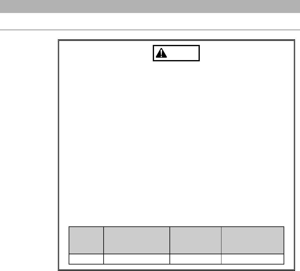
Blade
diameter
[inch]
Maximum spindle
rotating speed
[min
-1
(rpm)]
Time to reach
maximum
speed [s]
Time needed for
complete stop [s]
3 30,000 30 15
B-85
Safety precautions for mounting the hub mount (2.2 kW spindle) (Continued)
WARNING
- If the lock bolt is tightened to a torque smaller than specified, it may
come off to incur hub mount separation that could cause personal
injury or damage to the machine.
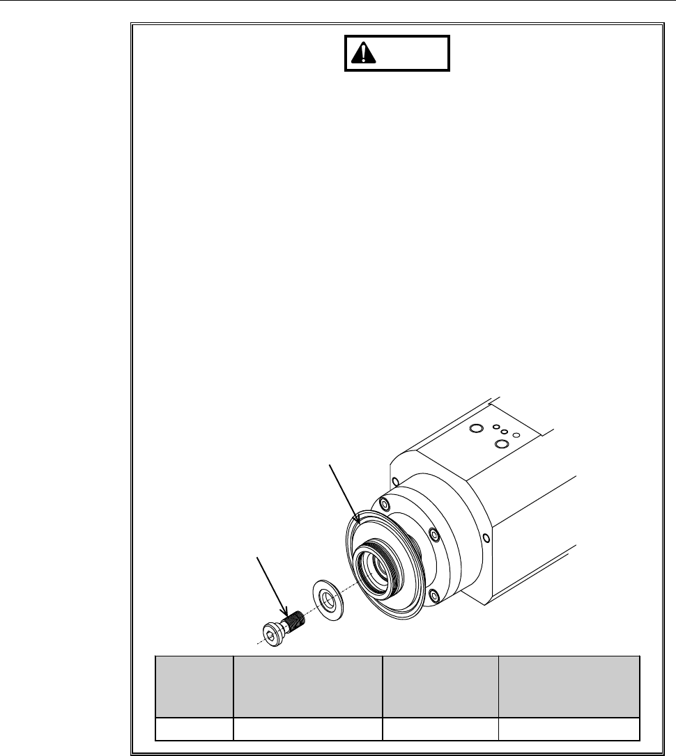
Tighten the lock bolt to the specified torque with the supplied torque
wrench.
[Procedures for tightening the lock bolt]
1: Torque the lock bolt to 8.0 N·m.
2: Close the cover.
3: Turn ON the spindle at the rotating speed to be used for cutting.
(Any button operation including turning OFF the spindle will be
deactivated until the rotating speed reaches the maximum.)
4: After the spindle rotation for sufficient time, turn OFF the spindle.
(Spindle rotations for too short time may cause flange loosing
while cutting. Take due account of the "Time to reach maximum
speed" in the table below.)
5: Torque the lock bolt to 8.0 N·m again.
Lock bolt
Hub mount
Blade
diameter
[inch]
Maximum spindle
rotating speed
[min
-1
(rpm)]
Time to reach
maximum
speed [s]
Time needed for
complete stop [s]
3 30,000 30 15