DFD6361-Maintenance.pdf - 第163页
B-91 3-1. Calli ng up t he CHANG E FRAME SIZE Screen [Screen 6 .1] Procedure s for calling up the CHANGE FRAME SIZE screen [screen 6.1] Step No. Do This 1 Press the <Sy stem Initial> button to effec t system initia…
B-90
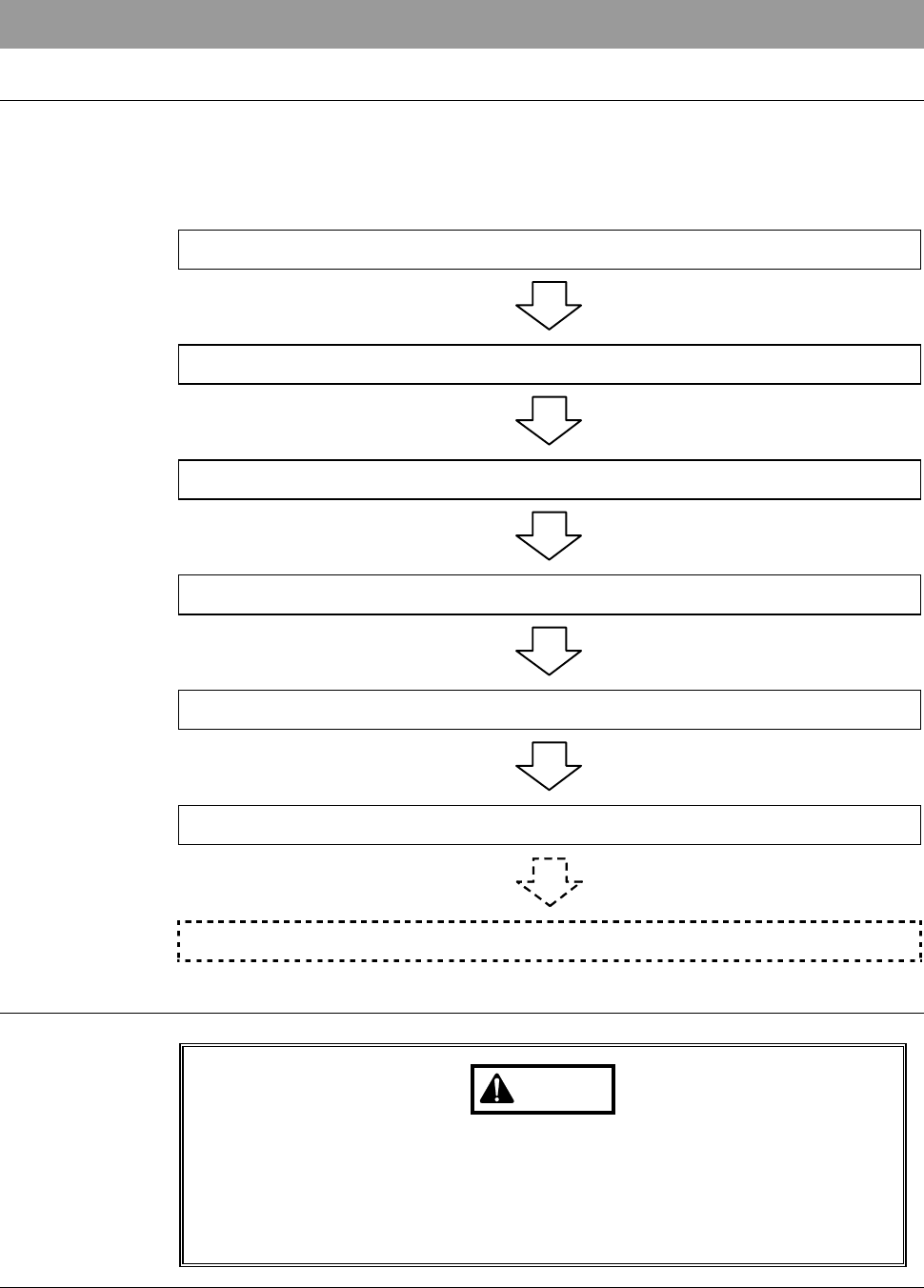
3. Changing the Frame Size
Operation flow
This section describes how to change the pad position of the lower arm and
upper arm, size of chuck table frame clamp and how to replace the spinner
table.
The procedure for changing the frame size consists of the following steps.
3-1 Calling up the CHANGE FRAME SIZE Screen
3-2 Changing the Lower Arm Size
3-3 Changing the Upper Arm Size
3-4 Replacing the Spinner Table
3-5 Changing the Frame Clamp Size
3-6 Completion of Frame Size Change
3-7 Changing UV Irradiation Unit Frame Size [Optional Accessory]
Safety precautions for changing the frame size
WARNING
If the touch panel control is activated to invoke an unexpected
machine operation, the operator may be injured.
While you don't use the touch panel, press the Disco's logo button
located at the upper left of the screen in order to lock up and
deactivate the touch panel.
B-91
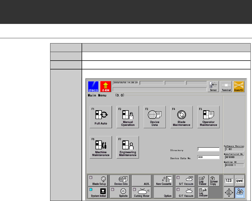
3-1. Calling up the CHANGE FRAME SIZE Screen
[Screen 6.1]
Procedures for calling up the CHANGE FRAME SIZE screen [screen 6.1]
Step No. Do This
1
Press the <System Initial> button to effect system initialization.
2
Make sure that the spindle system is OFF.
3
Call up the MAIN MENU screen [screen 0.0].
B-92
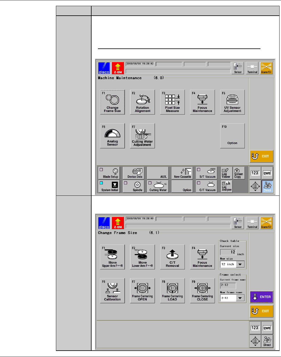
Procedures for calling up the CHANGE FRAME SIZE screen [screen 6.1] (Continued)
Step No. Do This
4
Press the <F6> button to call up the MACHINE
MAINTENANCE screen [screen 6.0].
- User password input is required to call up this screen.
- For the MACHINE MAINTENANCE screen [screen 6.0],
see the section B-6-1 of the Data Maintenance Manual.
5
Press the <F1> button to call up the CHANGE FRAME SIZE
screen [screen 6.1].
Continued in the next section.