DFD6361-Maintenance.pdf - 第164页
B-92 Procedure s for calling u p the CHANGE FRAME SIZE screen [screen 6.1] (Contin ued) Step No. Do This 4 Press the <F6 > button to cal l up the MACH INE MAINTENANCE screen [ screen 6.0]. - User password input is …
B-91
3-1. Calling up the CHANGE FRAME SIZE Screen
[Screen 6.1]
Procedures for calling up the CHANGE FRAME SIZE screen [screen 6.1]
Step No. Do This
1
Press the <System Initial> button to effect system initialization.
2
Make sure that the spindle system is OFF.
3
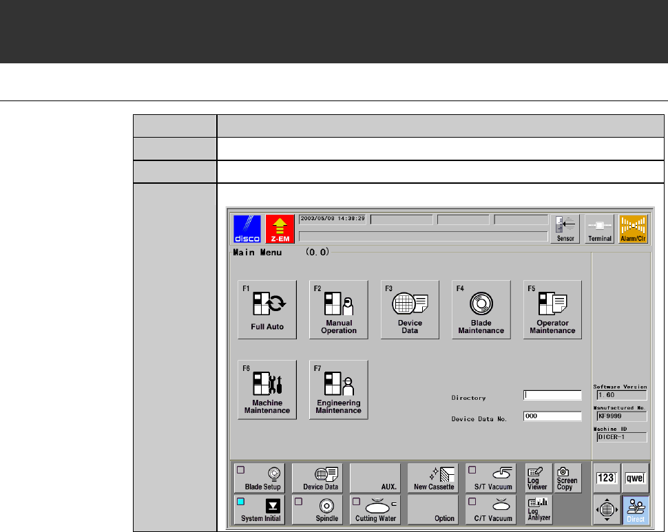
Call up the MAIN MENU screen [screen 0.0].
B-92
Procedures for calling up the CHANGE FRAME SIZE screen [screen 6.1] (Continued)
Step No. Do This
4
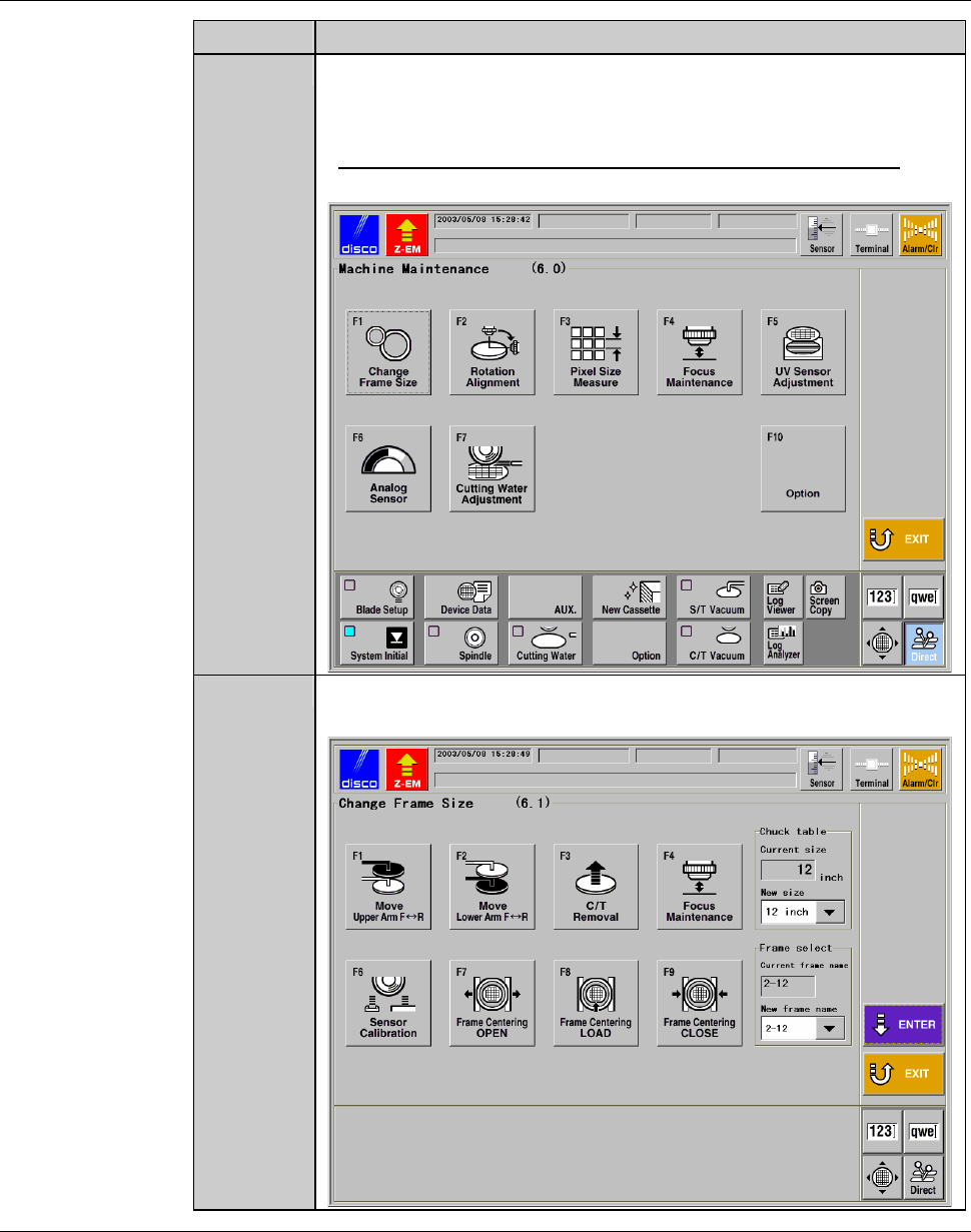
Press the <F6> button to call up the MACHINE
MAINTENANCE screen [screen 6.0].
- User password input is required to call up this screen.
- For the MACHINE MAINTENANCE screen [screen 6.0],
see the section B-6-1 of the Data Maintenance Manual.
5
Press the <F1> button to call up the CHANGE FRAME SIZE
screen [screen 6.1].
Continued in the next section.
B-93
3-2. Changing the Lower Arm Size
Procedures for changing the lower arm size
To change the size of the lower arm, slide the pad plates of the arm to the
position suitable for the frame to be used.
Step No. Do This
(Continued from the previous section)
1
Press the <F2> button from the CHANGE FRAME SIZE screen
[screen 6.1].
- The lower arm then moves to a location above the chuck table.
2
Visually make sure that all drive sections stop completely.
3
Open the front arm section cover.
4
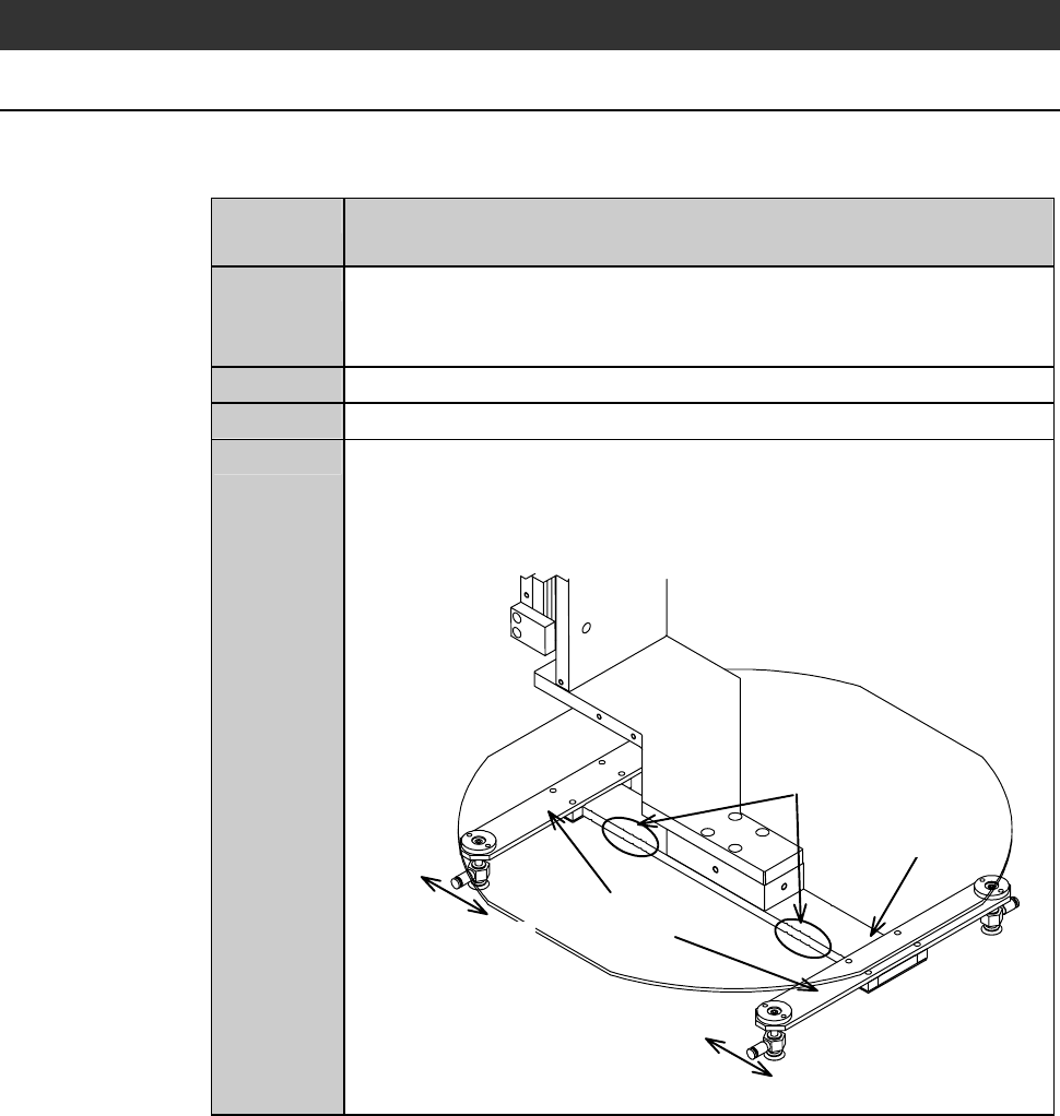
Change the lower arm pad position.
On the arm of the lower arm, there are the notches at a number of
places to suit various frame sizes. Slide the pad plates to the
suitable notch for the frame size to be used.
Notches
Arm
Sliding direction
Pad plates
Sliding direction