DFD6361-Maintenance.pdf - 第17页
A-1 A. MACHINE COMPONENTS AND FUNCTIONS Cont ents of t his ch apter This chapter describes the structure of this mac hine and the function and characteris tics of ea ch section. Section No. Titl e Contents 1 Machine Oute…

Contents-10
CONTENTS
5-4. Replacing the Controller for the Wheel Coolant Water Flow Rate................ F-122ÿ
5-4-1. Removing the machine outer cover .................................................... F-124ÿ
5-4-2. Disconnecting piping and wiring.......................................................... F-126ÿ
5-4-3. Replacing the controller for the wheel coolant water flow rate............ F-128ÿ
5-5. Replacing the Circuit Board of Electrical System due to
Battery Life End............................................................................................F-130ÿ
G. DATA SHEET ..................................................... G-1
1. Noise Level ............................................................................................G-2ÿ
2. Material Safety Data Sheet (MSDS).......................................................G-3ÿ
CHECK SHEET 1 - MAINTENANCE AND
PERIODIC INSPECTION -.....................Appendix-1
CHECK SHEET 2 - CONSUMABLE PARTS
REPLACEMENT -..................................Appendix-3
INDEX............................................................... Index-1
ADDRESS LIST
IN AN EVENT OF AN ACCIDENT
A-1
A. MACHINE COMPONENTS
AND FUNCTIONS
Contents of this chapter
This chapter describes the structure of this machine and the function and
characteristics of each section.
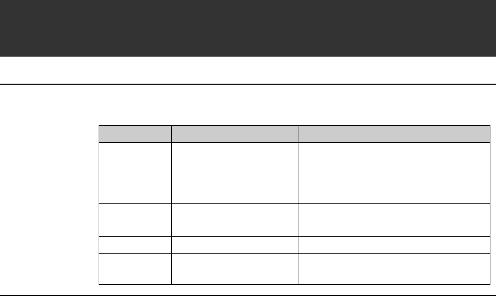
Section No. Title Contents
1 Machine Outer Cover - Configuration of the machine outer
cover
- Lock mechanism of the machine
outer cover
2 Axis Section - Axis arrangement
- Function of each axis
3 Main Body Section - Structure of the main body
4 Detection Function - Safety devices employed in this
machine
A-2
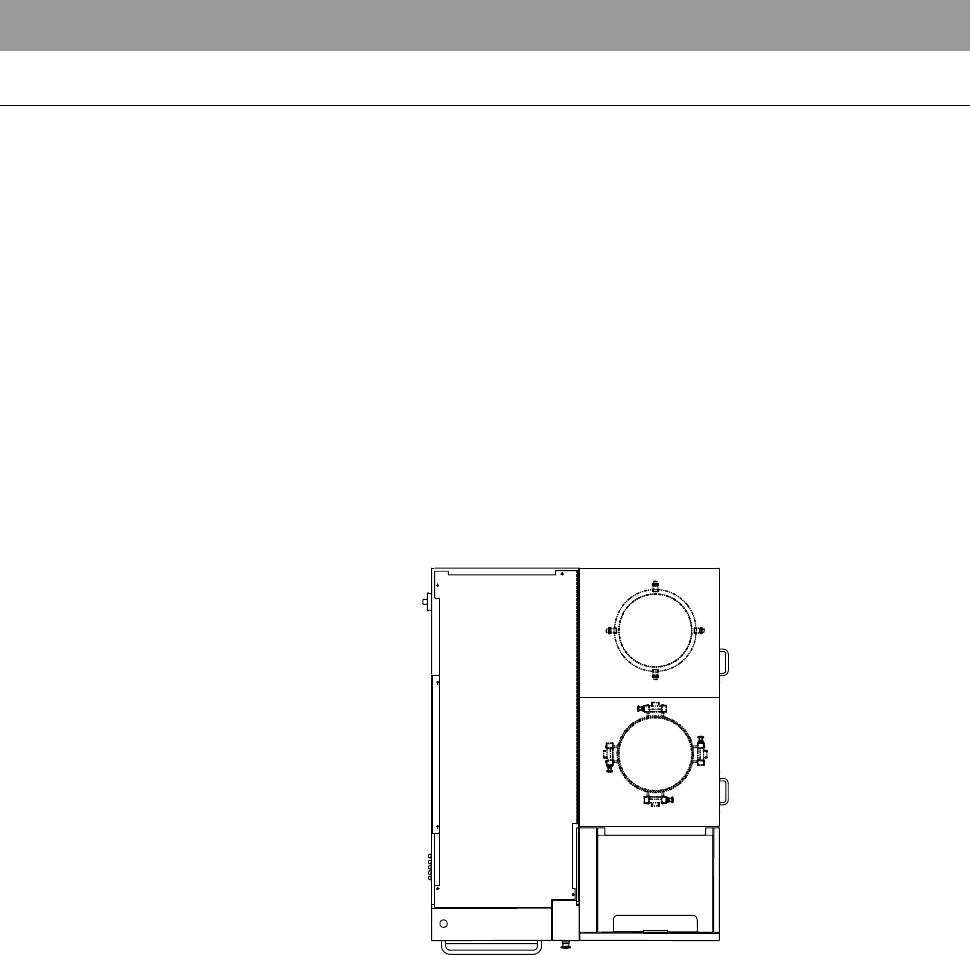
1. Machine Outer Cover
Machine outer cover configuration
The machine outer covers are configured as illustrated below.
Depending on the cover position, the covers are mounted by either of the
following two methods.
- Mounted with the outer cover lock
- Mounted with the mounting screw
To remove the covers mounted with the outer cover lock, you should release
the cover locks which are located at the positions as shown below.
For the procedure to release the cover lock, see [Machine outer cover lock
mechanism] in the next page.
- For the procedure to remove the machine outer cover;
See the section B-2-2, [Removing the Machine Outer Cover and Status
Indicator] of the Installation Manual.
TOP SIDE