DFD6361-Maintenance.pdf - 第172页
B-100 3-5. Ch anging the Frame Clamp S ize Procedur es for c hanging the frame c lamp siz e Step No. Do This (Continued from the previous section) 1 Press the <F1> button on the CHANGE FRAME S IZ E scre en [screen …

B-99
3-4-2. Mounting the spinner table
Procedures for mounting the spinner table
Step No. Do This
(Continued from the previous section)
1
With a lint-free cloth moistened with alcohol, clean the spinner
table to be installed and the table base.
2
Set the spinner table on the table base.
3
Screw down the all retaining screws of the spinner table.
4
Close the rear arm section cover.
Continued in the next section.
B-100
3-5. Changing the Frame Clamp Size
Procedures for changing the frame clamp size
Step No. Do This
(Continued from the previous section)
1
Press the <F1> button on the CHANGE FRAME SIZE screen
[screen 6.1].
- The upper arm moves to above the spinner table.
2
Press the <F2> button on the CHANGE FRAME SIZE screen
[screen 6.1].
- The lower arm moves to above the spinner table.
3
Visually make sure that all drive sections stop completely.
4
Open the front arm section cover.
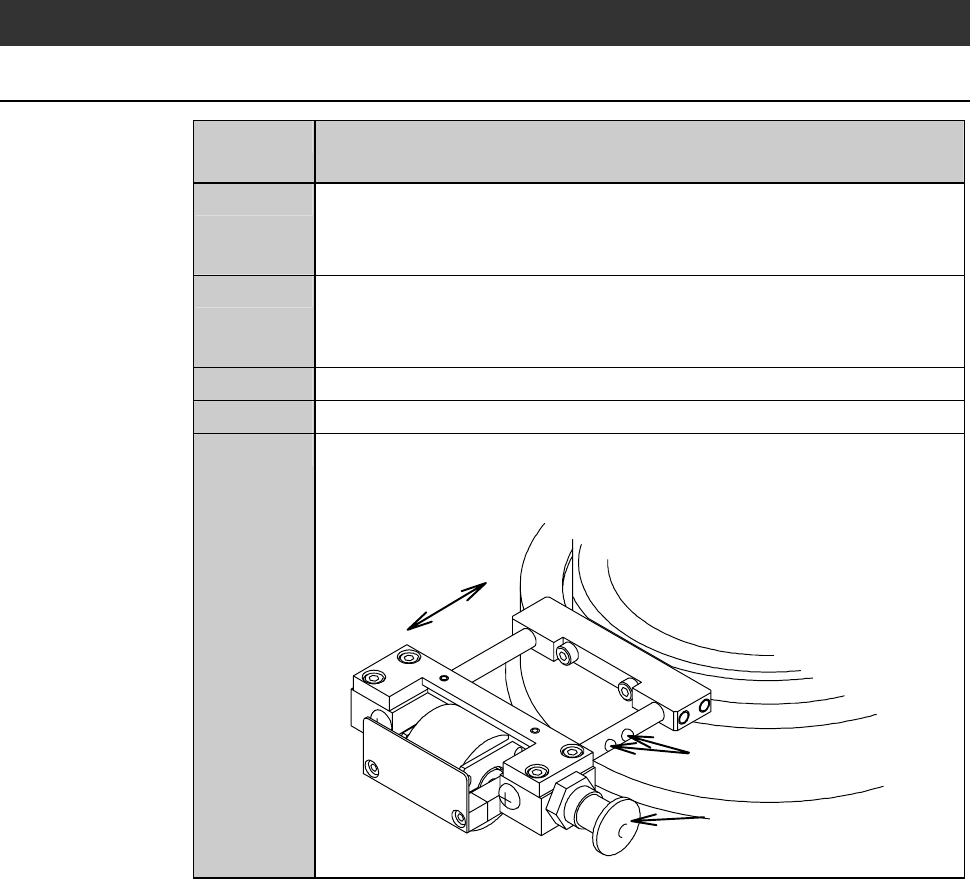
5
While pulling the frame clamp handle, which is located at the
side of the chuck table, slide the frame clamp to change its
position to suit the frame size to be used.
Frame size positioning holes
Frame clamp handle
* The frame clamp is unlocked
when the handle is pulled.
Sliding direction
B-101
Procedures for changing the frame clamp size (Continued)
Step No. Do This
5
(Continued)
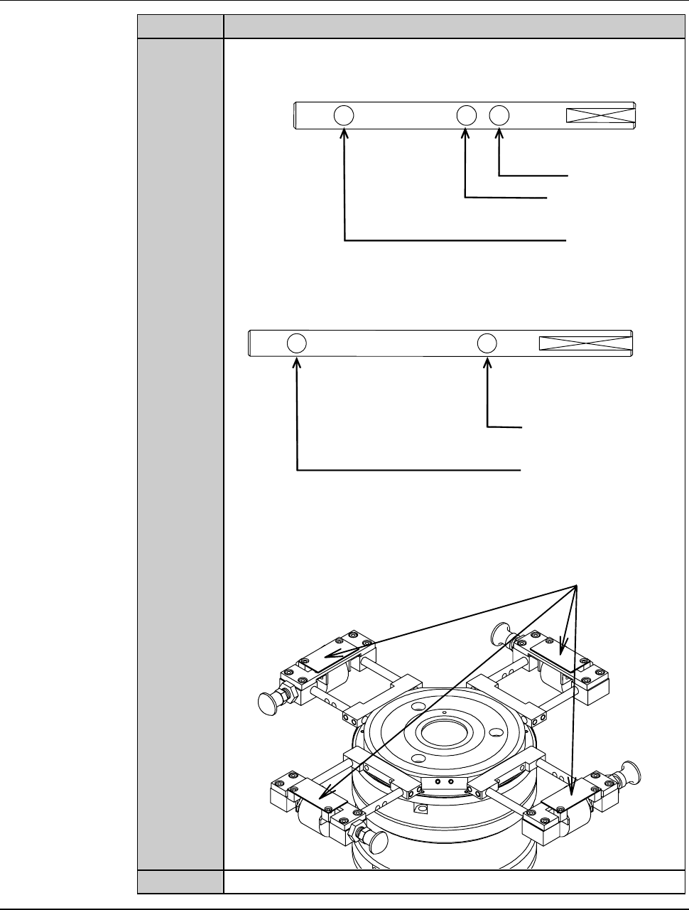
The locations of the frame size positioning holes are as shown
bellow.
for 2-6-1,2-6
for 2-5-1
for 2-8-1
[DFD6351]
for 2-8-1
for 212
[DFD6361]
Table base Table base
Four frame clamps are mounted on the chuck table.
Frame clamps
6
Close the front arm section cover.
Continued in the next section.