DFD6361-Maintenance.pdf - 第182页
B-110 3-7-4. Com pletion of the fram e size cha nge Procedures for com pletion of the frame siz e change Step No. Do This (Continued from the previous section) 1 Turn ON the facility p ow er source. 2 Open the cir cuit b…
B-109
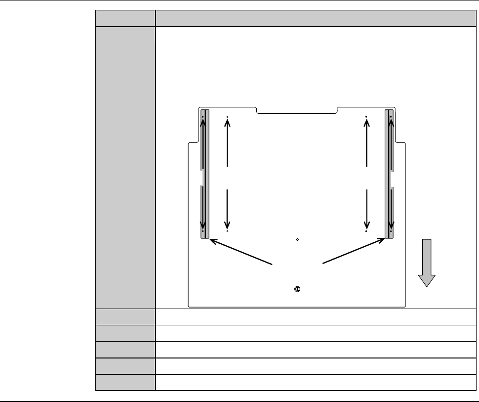
Procedures for changing the frame size (Continued)
Step No. Do This
4
Remove the guide on the backside of the inspection plate. Then
fit it to the position corresponding with the frame size.
- Make sure that the guide fits over the two mounting holes
correctly.
212
2-8-1
212
2-8-1
Guide
Front
Backside of the inspection plate
5
Reinstall the inspection plate to its the original position.
6
Attach the screw (M4) of the inspection plate.
7
Close the inspection cover.
8
Close the cassette stage.
9
Tighten the retaining screw of the cassette stage.
Continued in the next section.

B-110
3-7-4. Completion of the frame size change
Procedures for completion of the frame size change
Step No. Do This
(Continued from the previous section)
1
Turn ON the facility power source.
2
Open the circuit breaker lever lock and turn ON the circuit
breaker.
3
Insert the key into the main switch and turn ON the main switch.
- The machine power is turned ON.

B-111
4. Sensor Adjustment
Summary of this section
This section describes the adjustment procedures for the pressure sensor.
Section No. Title Contents
4-1 Pressure Sensor - Description of the pressure
sensor
- Setting value of the pressure
sensor
- Procedures for adjusting the
pressure sensor
4-2 Air Pressure Sensor
Adjustment
- Procedure for adjusting the air
pressure sensor
4-3 Setting a Monitor Value
of clean air Pressure
- Procedure for setting a monitor
value of the clean air pressure
4-4 Setting a Monitor Value
of Deionized Water
Pressure
- Procedure for setting a monitor
value of the deionized water
pressure
4-5 Setting a Monitor Value
of Vacuum Pressure
- Vacuum pressure control
mechanism
- Procedure for setting a monitor
value of the vacuum pressure