DFD6361-Maintenance.pdf - 第216页
C-4 ENGINEERING MAINTENANCE screen [scr een 7.0] [Screen] [Function Butto n] Press To F1 Call up the FRANGE DRESSING screen [s creen 7.1]. F2 Call up the AXI S OPERATION screen which is used to che ck the axis operations…
C-3
1. Calling up ENGINEERING MAINTENANCE
Screen [Screen 7.0]
Summary of this section
This section describes the procedures to call up the ENGINEERING
MAINTENANCE screen [screen 7.0] and the detailed information of this
screen.
Procedures to call up ENGINEERING MAINTENANCE screen [screen 7.0]
Step No. Do This
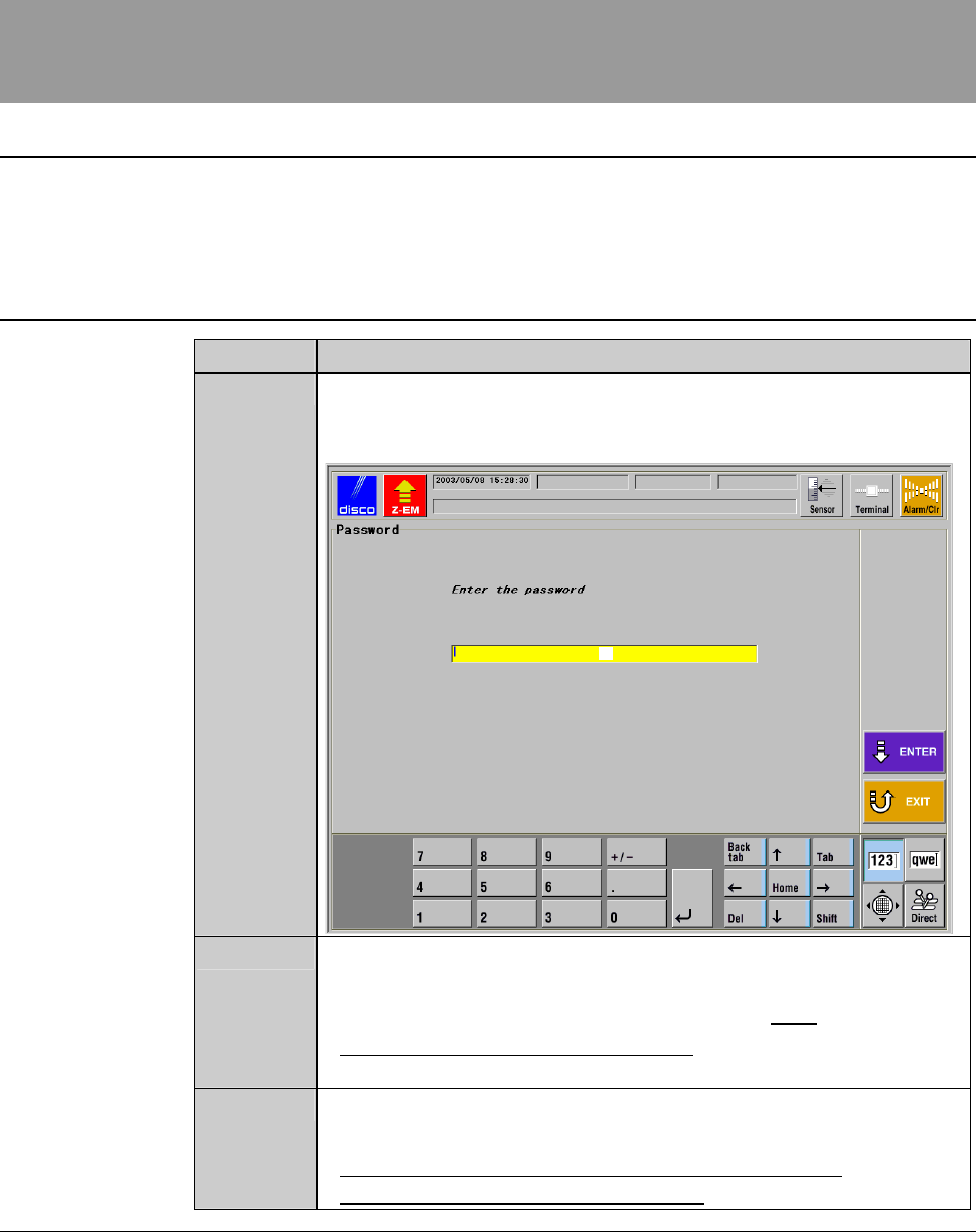
1
From the MAIN MENU screen [screen 0.0], press the <F7>
button.
- The PASSWORD screen then appears.
[1]
2
Input the engineering password in the input space [1], and then
press the <ENTER> button.
- The factory preset engineering password is "123".
- To change the engineering password, see the section 5 of this
chapter, [Customizing Setting].
3
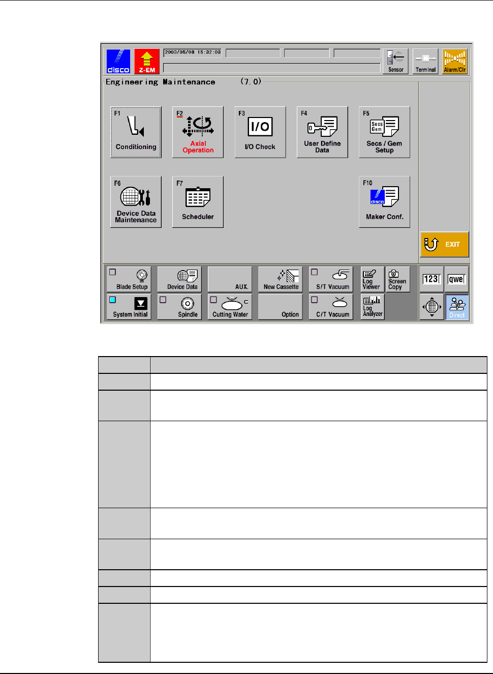
The ENGINEERING MAINTENANCE screen [screen 7.0]
appears only when the entered password is correct.
- For the detailed information of the ENGINEERING
MAINTENANCE screen [screen 7.0], see the next page.
C-4
ENGINEERING MAINTENANCE screen [screen 7.0]
[Screen]
[Function Button]
Press To
F1
Call up the FRANGE DRESSING screen [screen 7.1].
F2
Call up the AXIS OPERATION screen which is used to check the
axis operations.
F3
Call up the I/O CHECK screen which is used to check the
conditions of the solenoid valve or sensor.
Among I/O CHECK screens, there are the DIGITAL OUTPUT
screen to activate the solenoid valve, the DIGITAL INPUT screen
to check the conditions of the sensor or the like and AXIS
SENSOR STATUS screen to verify the axis sensor conditions.
F4
Call up the USER DEFINE DATA screen [screen 7.4] which
allows you to select various function setup data.
F5
Call up the screen which accept starting and setting the
SECS/GEM.[User-specified specification]
F6
Call up the DEVICE DATA MAINTENANCE screen.
F7
Call up the MAINTENANCE SCHEDULER screen.
F10
Call up the MAKER DATA screen.
(The input of the maker password is required for displaying the
MAKER DATA screen, which is to be handled by the DISCO
maintenance personnel only.)
C-5
2. Hub Mount/Flange Conditioning
About conditioning
The term "conditioning" refers to the operations performed to dress a blade
contact surface of a hub mount or flange.
The contact surface accuracy of the flange A (rear flange) is particularly
important. The low accuracy of this surface gives an adverse effect on the
machining precision, which results in a tapered shaped cutting slot, an
excessive kerf width or a blade breakage.
WARNING
- For conditioning purposes, you have to operate the X-, Y- and Z-
axes while the cover is open with its interlock disabled by the
maintenance switch.
Conditioning must be carried out by the qualified maintenance
personnel who have a good understanding of safety precautions.
- If any unexpected machine operation is inadvertently invoked
during conditioning, the maintenance personnel may be injured.
While you don't use the touch panel, press the Disco's logo button
located at the upper left of the screen in order to lock up and
deactivate the touch panel.
Summary of this section
This section describes the conditioning operation in the following sub-sections.
Section No. Title Contents
2-1 Movement in
Conditioning
- Movement in conditioning of
flange and hub mount
- Shape of the end face after
conditioning
2-2 Executing Conditioning - Procedures for executing the
conditioning