DFD6361-Maintenance.pdf - 第223页
C-11 2-2-1. Re placing t he chuck tab le Procedur es for replaci ng the chuck tabl e For conditioning purposes, replace the currently installed chuck ta ble with the chuck table for dressing. Step No. Do This 1 Carry out…
C-10
Before operation
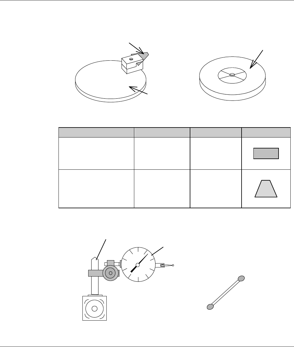
Have on hand the following jigs for conditioning operation.
[Conditioning tools]
Conditioning jig
Conditioning tip
Chuck table for dressing
[Conditioning tip]
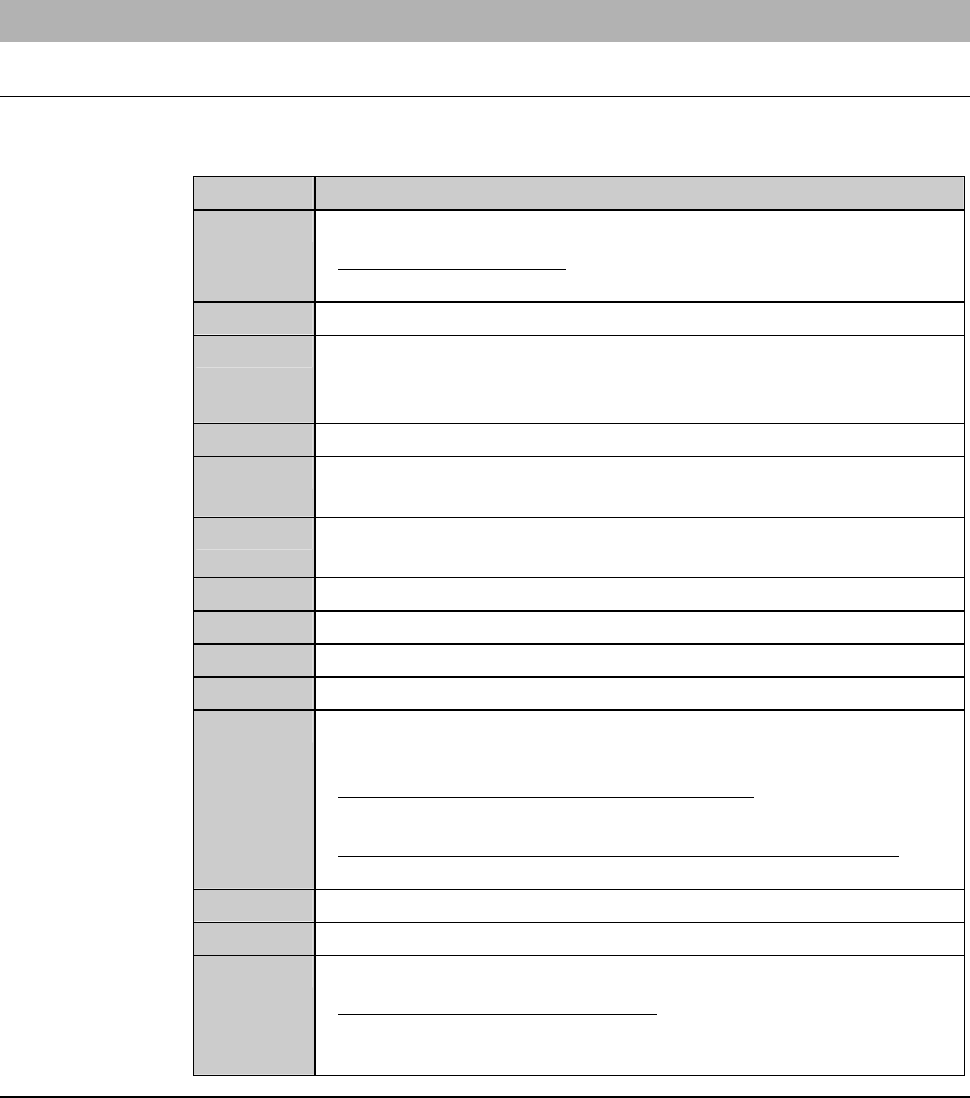
Purpose Parts No. Color Shape
Flange conditioning MODBN765 Black
Hub mount
conditioning
MODBN890 Dark brown
[Measuring equipment]
Magnet stand
Dial gauge
Cotton swab moistened
with alcohol
*) The dial gauge must be calibrated in increments of 2 µ m or less.
C-11
2-2-1. Replacing the chuck table
Procedures for replacing the chuck table
For conditioning purposes, replace the currently installed chuck table with the
chuck table for dressing.
Step No. Do This
1
Carry out the setup operation.
- For the setup operation;
See the section B-7, [Setup] of the Operation Manual.
2
Call up the MACHINE MAINTENANCE screen [screen 6.0].
3
From the MACHINE MAINTENANCE screen [screen 6.0],
press the <F1> button to call up the CHANGE FRAME SIZE
screen [screen 6.1].
4
Make sure that the spindle rotation and all axes stop.
5
If the wheel coolant water is ON, press the <Cutting Water>
buttontoturnitOFF.
6
From the CHANGE FRAME SIZE screen [screen 6.1], press the
<F3> button to turn OFF the vacuum of chuck table.
7
Open the front arm section cover.
8
Remove the chuck table.
9
Set the chuck table for dressing on the table base.
10
Verify the chuck table position.
11
Turn ON the vacuum system by pressing the <F3> button to
secure the chuck table.
- For the chuck table replacement procedure;
See the section B-1, [Chuck Table Replacement].
- For the MACHINE MAINTENANCE screen [screen 6.0];
See the section B-6-1 of the Data Maintenance Manual.
12
Close the front arm section cover.
13
Press the <System Initial> button to effect system initialization.
14
If any blade is installed over the Z1- and Z2-axis, remove them.
- For the blade removal procedure;
See the section B-6, [Blade Maintenance] of the Operation
Manual.
Continued in the next section.
C-12
2-2-2. Verifying FLANGE DRESSING screen data
Procedures for verifying FLANGE DRESSING screen data
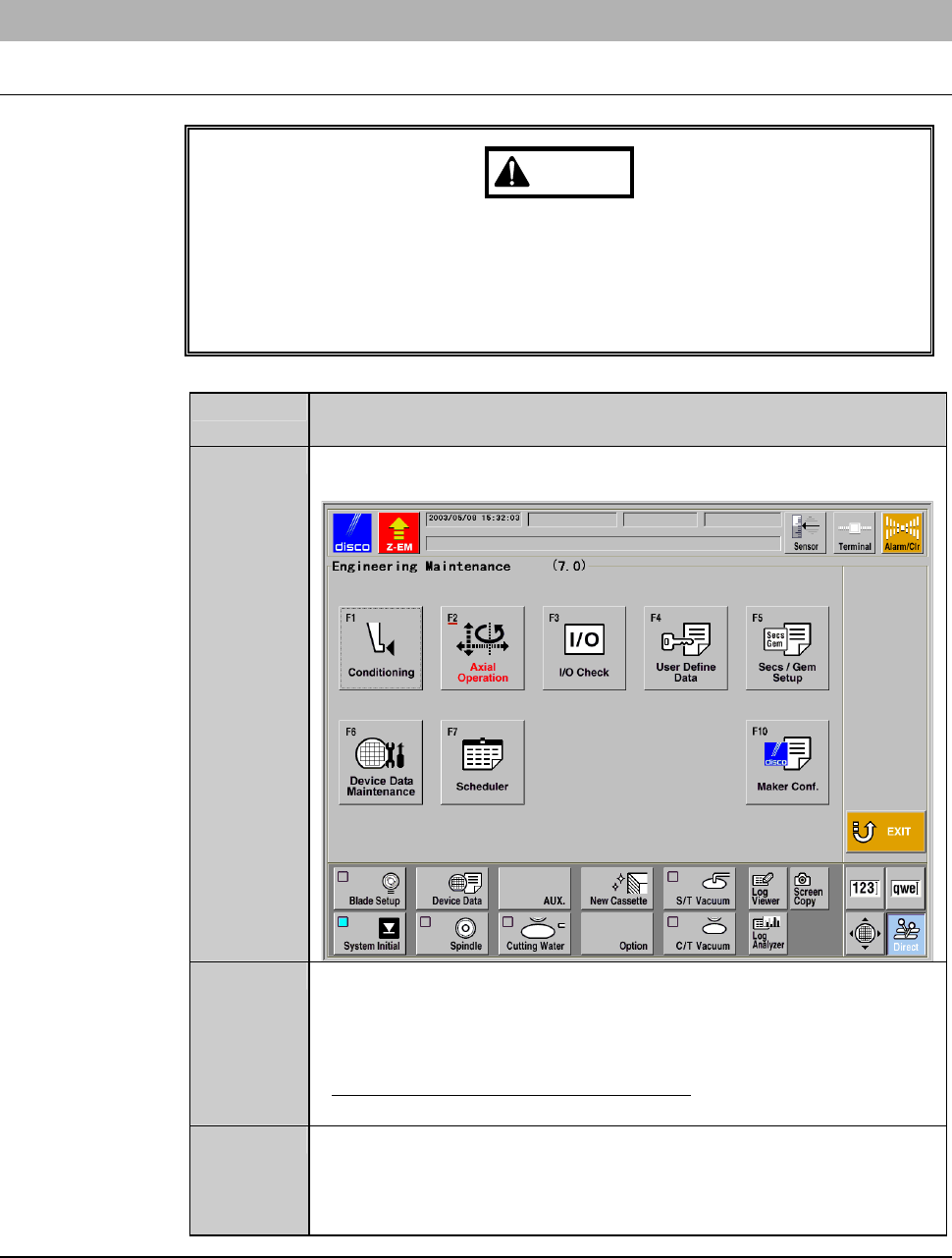
WARNING
If the <F1> button is pressed from the ENGINEERING
MAINTENANCE screen [screen 7.0], the chuck table for dressing
automatically moves to under the spindle. If you place your fingers or
hands in the drive section, they may be caught or cut off.
Do not position your fingers and hands in the drive section.
Step No. Do This
(Continued from the previous section)
1
Call up the ENGINEERING MAINTENANCE screen
[screen 7.0].
2
Press the <F1> button.
- The chuck table then moves to under the spindle.
- The wheel cover opens.
- The FLANGE DRESSING screen [screen 7.1] is displayed.
- For the FLANGE DRESSING screen;
See FLANGE DRESSING screen [screen 7.1] in the next page.
3
Confirm the data displayed on the FLANGE DRESSING screen
[screen 7.1].
- To change the data setup, enter desired data with numeric
buttons and then press the <ENTER> button.
Continued in the next section.