DFD6361-Maintenance.pdf - 第225页
C-13 W he n y ou abort t he ver ifying procedures W ARNING If the <EX IT> button is pr essed from the FLAN GE DRESSING screen [screen 7.1], th e chuck table automatically moves to the origin position ( right). If y…
C-12
2-2-2. Verifying FLANGE DRESSING screen data
Procedures for verifying FLANGE DRESSING screen data
WARNING
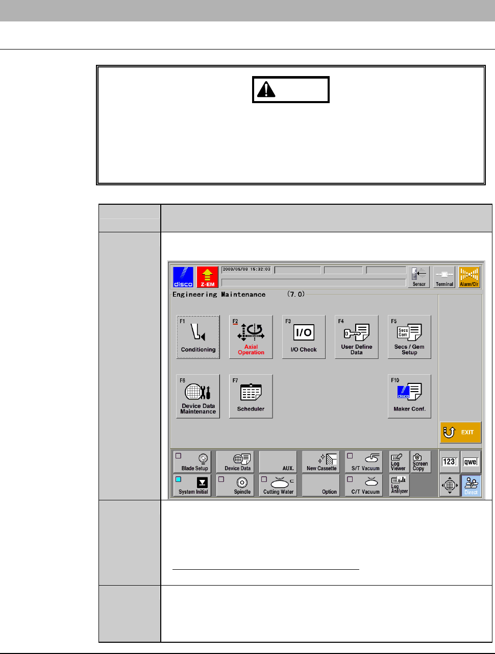
If the <F1> button is pressed from the ENGINEERING
MAINTENANCE screen [screen 7.0], the chuck table for dressing
automatically moves to under the spindle. If you place your fingers or
hands in the drive section, they may be caught or cut off.
Do not position your fingers and hands in the drive section.
Step No. Do This
(Continued from the previous section)
1
Call up the ENGINEERING MAINTENANCE screen
[screen 7.0].
2
Press the <F1> button.
- The chuck table then moves to under the spindle.
- The wheel cover opens.
- The FLANGE DRESSING screen [screen 7.1] is displayed.
- For the FLANGE DRESSING screen;
See FLANGE DRESSING screen [screen 7.1] in the next page.
3
Confirm the data displayed on the FLANGE DRESSING screen
[screen 7.1].
- To change the data setup, enter desired data with numeric
buttons and then press the <ENTER> button.
Continued in the next section.
C-13
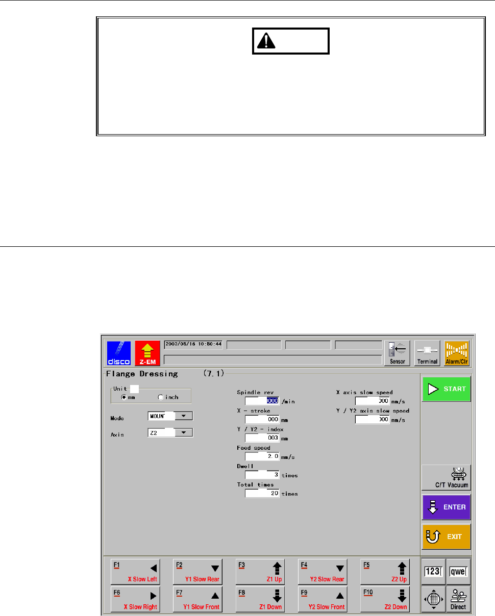
When you abort the verifying procedures
WARNING
If the <EXIT> button is pressed from the FLANGE DRESSING
screen [screen 7.1], the chuck table automatically moves to the origin
position (right). If you place your fingers or hands in the drive section,
they may be caught or cut off.
Do not insert your fingers or hands in the drive section.
To abort the procedures of verifying screen data, press the <EXIT> button.
- Pressing the <EXIT> button cancels any edits on the data setup and causes
the chuck table (X-axis) to return to the origin (zero-point position).
- The display returns to the ENGINEERING MAINTENANCE screen
[screen 7.0].
FLANGE DRESSING screen [screen 7.1]
This screen is used to setup data for performing flange/wheel mount
conditioning and execute conditioning operation.
The screen below is an example data setup.
[Screen]
[1]
[2]
[3]
[4]
[5]
[6]
[7]
[8]
[9]
[10]
[11]
C-14
FLANGE DRESSING screen [screen 7.1] (Continued)
[Setting Item]
Item No. Descriptions
[1]
Select the unit of measure (inch or millimeter)..
[2]
Select either MOUNT or FLANGE.
[3]
Specify the spindle axis to perform conditioning.
[4]
Enter the number of spindle revolution for conditioning.
[5]
Enter the amount of X-axis movement for conditioning.
- Enter the conditioning chip travel distance data.
[6]
Enter the amount of Y-axis movement for conditioning.
- An entry exceeding 0.01 mm will not be accepted.
[7]
Enter the X-axis feed speed data.
[8]
Enter the counts of spark-out.
[9]
Enter the counts of grinding operation to be performed, taking one
spark-out cycle to constitute one grinding operation.
[10]
Set the X-axis feed speed when using the <F1> and <F6> buttons.
[11]
Set the Y1- and Y2-axis feed speed when using the <F2>, <F4>,
<F7> and <F9> buttons.
[Function Button]
Press To
F1
Move (scan) the X-axis to the left at low speed.
F2
Move (scan) the Y1-axis to the rear at low speed.
F3
Raise (scan) the Z1-axis.
F4
Move (scan) the Y2-axis to the rear at low speed.
F5
Raise (scan) the Z2-axis.
F6
Move (scan) the X-axis to the right at low speed.
F7
Move (scan) the Y1-axis to the front at low speed.
F8
Lower(scan)theZ1-axis.
F9
Move (scan) the Y2-axis to the front at low speed.
F10
Lower(scan)theZ2-axis.