DFD6361-Maintenance.pdf - 第230页
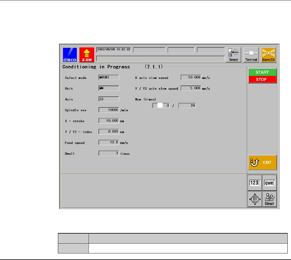
C-18 CONDITIONING IN PROGRESS screen [screen 7.1.1] While the conditioning is executed, the CONDITIONING IN PROGRESS screen [screen 7.1.1] is displayed. [Screen] ÿ [1] [Setting Ite m] Item No. Descriptions [1] Shows the …
C-17
Procedures for executing conditioning (Continued)
Step No. Do This
5
Mount the conditioning jig on the chuck table for dressing.
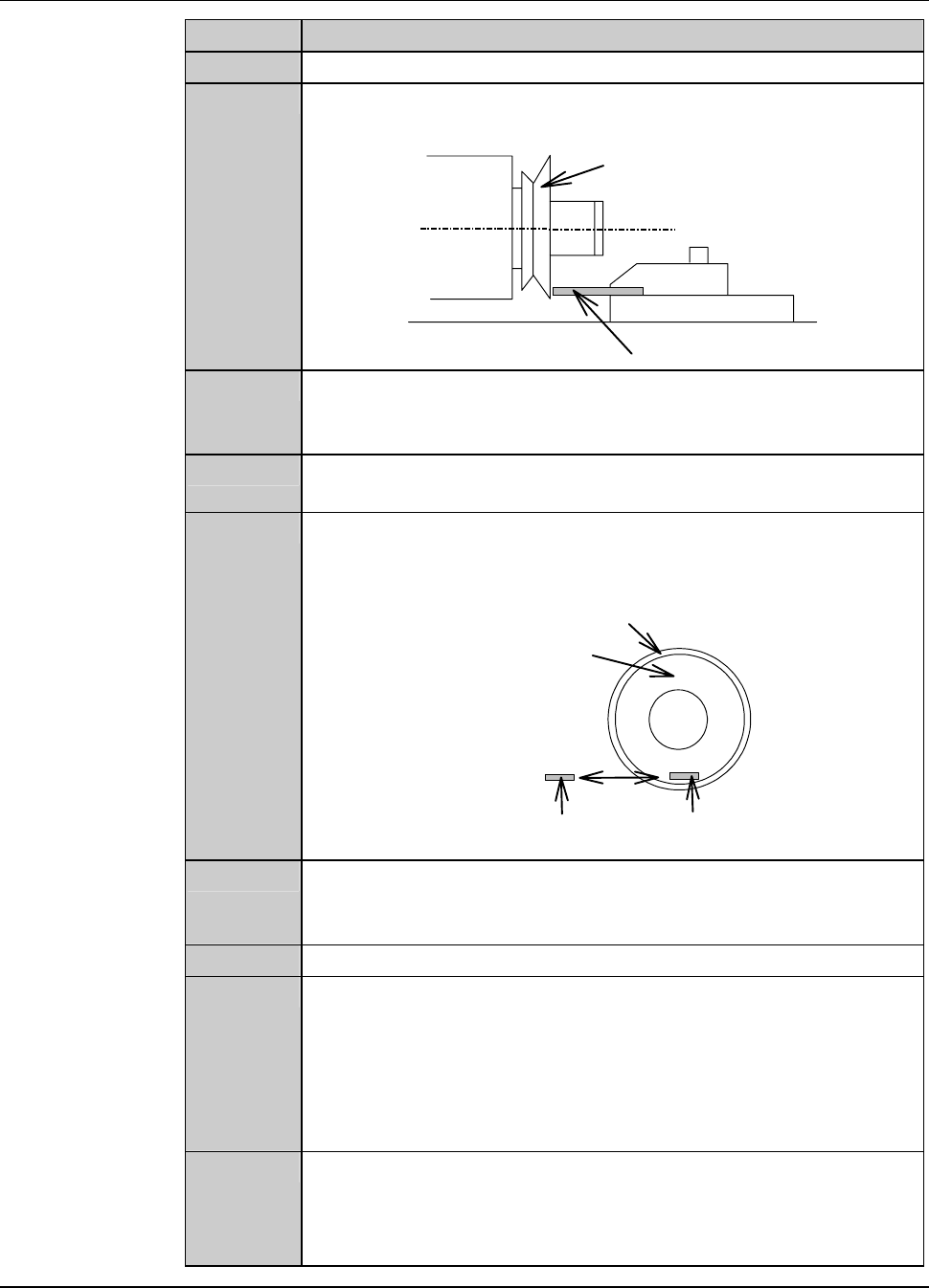
6
Move the Z-axis to the location shown below by using the axis
operation button.
Conditioning jig
Conditioning chip
Flange/Wheel mount
7
Using the axis operation button, move the Y-axis to the location
where the conditioning chip touches the flange or wheel mount
end face lightly.
8
Turn ON the vacuum system by pressing the <C/T Vacuum>
button to secure the conditioning jig.
9
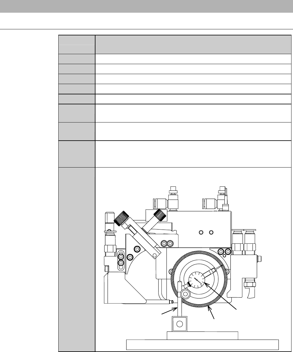
Move the X-axis to the conditioning start position shown below.
- The resultant axis position setup provides the conditioning start
position.
End face
Conditioning start
position
Conditioning chip
Flange/Wheel mount
10
Check the value of [X-stroke] on the FLANGE DRESSING
screen [screen 7.1] and make sure that the conditioning jigs do
not collide against the wheel cover nozzle.
11
Close the splash cover.
12
Press the <START> button.
- The spindle starts rotating to automatically initiate a
conditioning operation.
- The display goes back to the CONDITIONING IN PROGRESS
screen [screen 7.1.1].
- During a pause, the X-axis is at the conditioning start position.
13
When the operation has been executed the pre-selected number
of times, the spindle stops.
- The display goes back to the FLANGE DRESSING screen
[screen 7.1].
Continued in the next section.
C-18
CONDITIONING IN PROGRESS screen [screen 7.1.1]
While the conditioning is executed, the CONDITIONING IN PROGRESS
screen [screen 7.1.1] is displayed.
[Screen]
ÿ
[1]
[Setting Item]
Item No. Descriptions
[1]
Shows the cycle counts of conditioning that have been performed.
C-19
2-2-4. Checking the end face accuracy
Procedures for checking the end face accuracy
Step No. Do This
(Continued from the previous section)
1
Make sure that the spindle rotation and all axes stop.
2
Turn the maintenance switch clockwise.
3
While pressing the maintenance button, open the splash cover.
4
Press the <C/T Vacuum> button to turn OFF the vacuum system.
5
Remove the conditioning jig.
6
Wipe the conditioned face of flange/hub mount clean with a
cotton swab moistened with alcohol.
7
Set a dial gauge on a magnet stand and fasten them on the
conditioning jig.
8
Place the conditioning jig with the dial gauge at the center of the
chucktable.Thenpressthe<C/TVacuum>buttontoturnON
the vacuum system.
9
Move the X- and Y-axes slowly so that the dial gauge end is
brought into contact with the end face.
Dressing chuck table
Conditionin
gj
i
g
End face
Magnetic stand
Dial gauge