DFD6361-Maintenance.pdf - 第232页
C-20 Procedur es for checkin g the end face accurac y (C ontinued) Step No. Do This 10 Gently rotate the spindle axi s clockwise by hand to check for dial gauge pointer deflection. - For wheel mount: 1 µ mo rl e s s -F o…
C-19
2-2-4. Checking the end face accuracy
Procedures for checking the end face accuracy
Step No. Do This
(Continued from the previous section)
1
Make sure that the spindle rotation and all axes stop.
2
Turn the maintenance switch clockwise.
3
While pressing the maintenance button, open the splash cover.
4
Press the <C/T Vacuum> button to turn OFF the vacuum system.
5
Remove the conditioning jig.
6
Wipe the conditioned face of flange/hub mount clean with a
cotton swab moistened with alcohol.
7
Set a dial gauge on a magnet stand and fasten them on the
conditioning jig.
8
Place the conditioning jig with the dial gauge at the center of the
chucktable.Thenpressthe<C/TVacuum>buttontoturnON
the vacuum system.
9
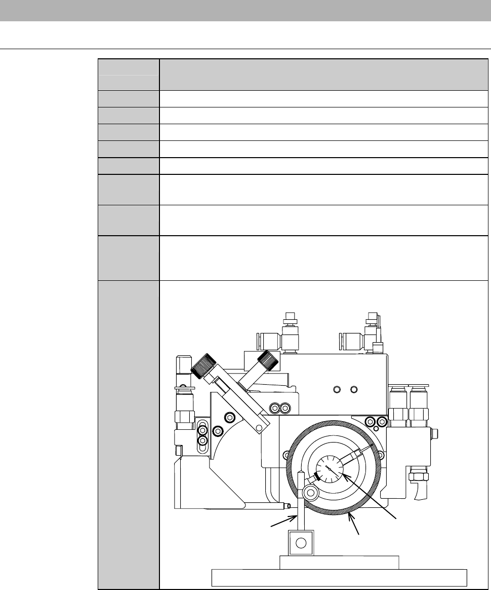
Move the X- and Y-axes slowly so that the dial gauge end is
brought into contact with the end face.
Dressing chuck table
Conditionin
gj
i
g
End face
Magnetic stand
Dial gauge
C-20
Procedures for checking the end face accuracy (Continued)
Step No. Do This
10
Gently rotate the spindle axis clockwise by hand to check for dial
gauge pointer deflection.
- For wheel mount: 1µmorless
-Forflange:3µmorless
If an end face run out is larger than these maximum limits;
Remove the dial gauge from the chuck table and repeat
conditioning procedures described in the section 2-2-3 of this
chapter, [Executing conditioning] and thereafter.
Continued in the next section.
C-21
2-2-5. Completion of conditioning
Procedures for completion of conditioning
CAUTION
If the <EXIT> button is pressed to cancel the conditioning mode with
jigs or other items left on the chuck table, the microscope or air
curtain may be damaged.
After conditioning, remove jigs, dial gauge and other items from the
chuck table upper surface, and then press the <EXIT> button.
Step No. Do This
(Continued from the previous section)
1
Remove the conditioning jig and dial gauge from the chuck table
upper surface.
2
Close the splash cover.
3
Press the <EXIT> button.
- The X- and Y-axes move to their origins.
- The display returns to the ENGINEERING MAINTENANCE
screen [screen 7.0].
4
Make sure that the spindle rotation and all axes stop.
5
Replace the chuck table for dressing with the work cutting chuck
table.
- For the chuck table replacement procedure;
See the section B-1, [Chuck Table Replacement].
6
Make sure that the chuck table is firmly secured.
When it is not secured;
Open the CHANGE FRAME SIZE screen [screen 6.1] and
press the <F3> button to secure the chuck table.
7
Pull off the maintenance key from the maintenance switch.
8
Have the maintenance key properly stored by the maintenance
personnel.
9
Install the blade and perform the following setup operation.
- For the standard machine: Conduct the contact setup.
- For the machine incorporating the non-contact setup feature
[optional accessory]: Conduct the sensor calibration setup.
- For setup procedures;
See the section B-7, [Setup] of the Operation Manual.