DFD6361-Maintenance.pdf - 第238页
C-26 AXIS OPERATION scr een (Continued) [Function Butto n] Press To F1 Unused F2 Execute a low-speed index operation in the minus direction. F3 Execute an index operation in t he minus direction. F4 Execute a low-speed s…
C-25
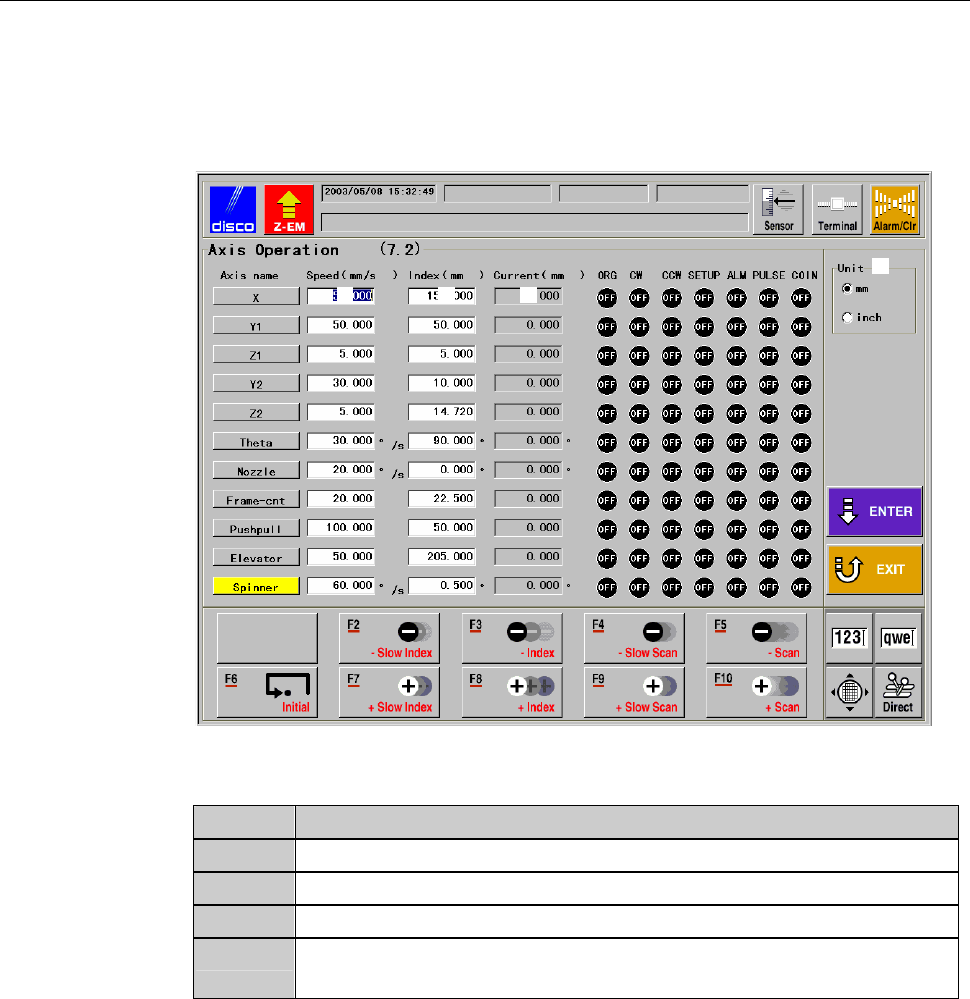
AXIS OPERATION screen
The description of AXIS OPERATION screen is as follows:
This screen is called up by pressing the <F2> button from ENGINEERING
MAINTENANCE screen [screen 7.0].
[Screen]
[1]
[2] [3] [4]
[Setting Item]
Item No. Descriptions
[1]
Select the unit of measure (inch or millimeter).
[2]
Enter the axis scan speed for the operation check of each axis.
[3]
Enter the axis index amount for the operation check of each axis.
[4]
Indicates the current position of each axis in the axis operation
check process.
C-26
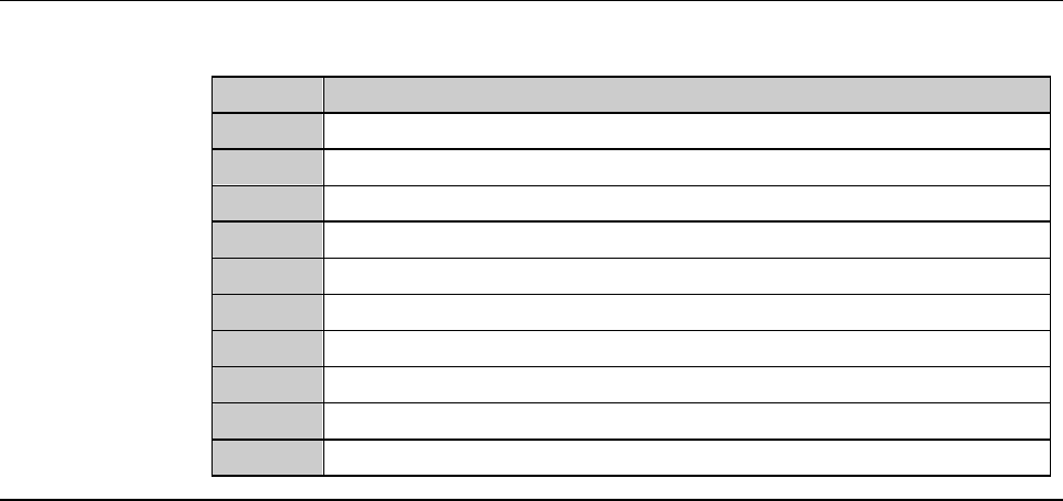
AXIS OPERATION screen (Continued)
[Function Button]
Press To
F1
Unused
F2
Execute a low-speed index operation in the minus direction.
F3
Execute an index operation in the minus direction.
F4
Execute a low-speed scan operation in the minus direction.
F5
Execute a scan operation in the minus direction.
F6
Effect initialization.
F7
Execute a low-speed index operation in the plus direction.
F8
Execute an index operation in the plus direction.
F9
Execute a low-speed scan operation in the plus direction.
F10
Execute a scan operation in the plus direction.
C-27
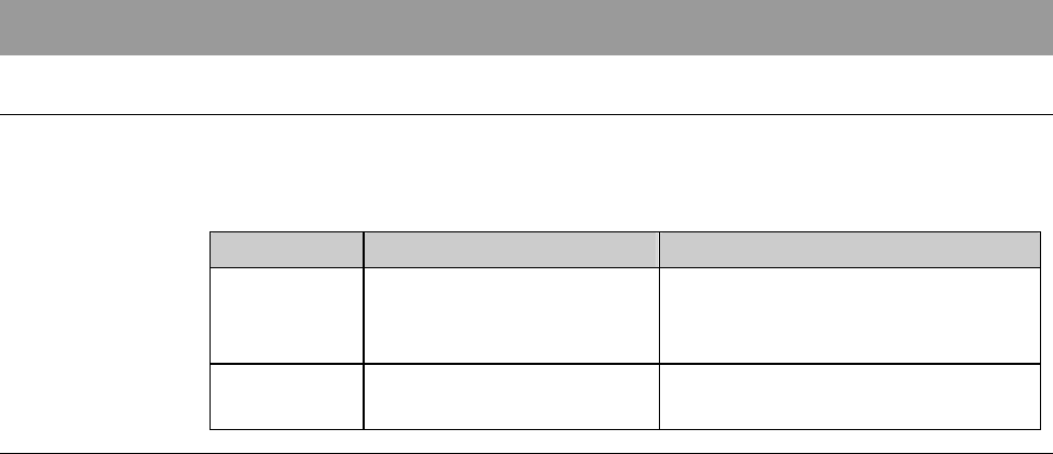
4. Sensor/Solenoid Valve Check
Summary of this section
This section describes the methods to check the machine abnormalities by
inspecting the operation of each sensor and solenoid valve. This section also
explains the methods to check each axis sensor status.
Section No. Title Contents
4-1 I/O Check - The ways to abnormality check
by individually operating each
sensor and solenoid valve
4-2 Axis Sensor Check - The ways to check for each axis
sensor status