DFD6361-Maintenance.pdf - 第251页
C-39 Procedur es for ax is sensor check (Contin ued) St e p N o . Do T his 1 From the ENGINEERING MA INTENANCE screen [screen 7.0], press the <F2> button. - The AXIS OPERA TION screen then app ears. Photointerrupte…
C-38
4-2. Axis Sensor Check
Summary of this section
This section explains the methods to check the axis sensor status.
If any abnormality is found in a sensor that is checked, such as an abnormal
operation, contact your DISCO Service Office.
Procedures for axis sensor check
WARNING
- In the axis sensor check procedures, in some cases, you may have
to operate an axis by using the maintenance key that disables the
axis driver power supply shutoff feature and deactivates the axis
interlock. This operation, therefore, may result in personnel injury or
damage of the machine.
This operation must be carried out carefully by the qualified
maintenance personnel.
- If the person other than the maintenance personnel touches the
machine, the machine operates and the maintenance personnel
may be injured.
Ensure that no person other than the maintenance personnel
touches the machine.
While you don't use the touch panel, press the Disco's logo button
located at the upper left of the screen in order to lock up and
deactivate the touch panel.
C-39
Procedures for axis sensor check (Continued)
Step No. Do This
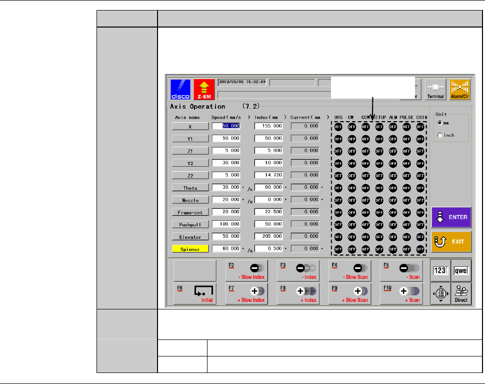
1
From the ENGINEERING MAINTENANCE screen [screen 7.0],
press the <F2> button.
- The AXIS OPERATION screen then appears.
Photointerrupter
status indication area
2
In the right-hand part of the AXIS OPERATION screen, the
current status of the photointerrupters of each axis are indicated.
ON The photointerrupter is ON.
OFF The photointerrupter is OFF.
C-40
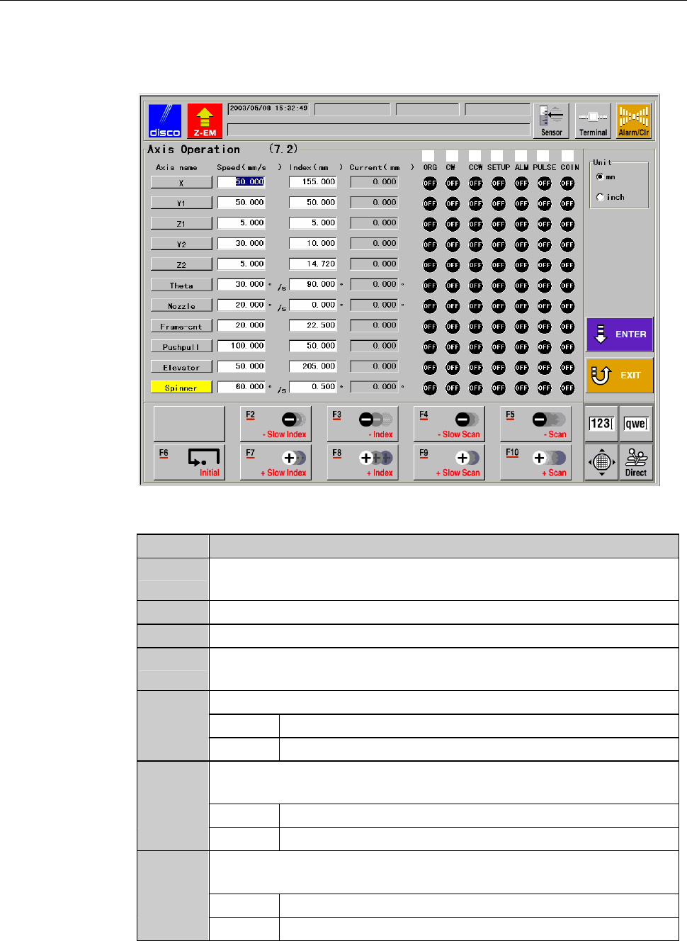
AXIS OPERATION screen - Photointerrupter status indication area
The description of the photointerrupter status indication area of theAXIS
OPERATOIN screen is as follows:
[Screen]
[1] [2] [3] [4] [5] [6] [7]
[Setting Item]
Item No. Descriptions
[1]
Shows ON or OFF to indicate the origin position sensor operation
status.
[2]
Shows ON or OFF to indicate the CW sensor operation status.
[3]
Shows ON or OFF to indicate the CCW sensor operation status.
[4]
Indicates whether the setup signal is ON or OFF (Z1- and Z2-
axis).
[5]
Indicates the axis alarm motor driver status.
ON Abnormal
OFF Normal
[6]
Shows ON or OFF to indicate whether the pulse output is being
generated (the axis is operating) or not.
ON Axis in motion
OFF Axis stopped
[7]
Indicates whether the COIN signal (positioning completion signal)
is ON or OFF.
ON The axis reaches the target position.
OFF The axis has not reached the target position.