DFD6361-Maintenance.pdf - 第26页
A-10 Axis arrang ement (C ontinued) Upp er arm section Spinner sec tion Lowe r arm secti on Pus h-pull a rm section Cassette stage Elevator section Fr am e c ent eri ng se ct ion Inspecti on W ork piece Door
A-9
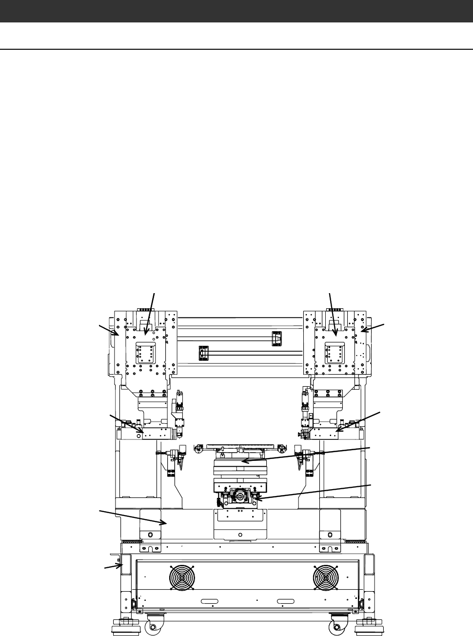
2-1. Axis Arrangement
Axis arrangement
As shown below, the machine consists of the X-axis section, Y (Y1 and Y2)-
axis section, Z (Z1 and Z2)-axis section, θ-axis section, spindle (spindle1 and
spindle2)-axis section, spinner section, elevator section, lower arm section,
upper arm section, push-pull arm section, frame centering section, main body
base, electrical system section and main body frame.
- The X-axis consists of the highly straight linear guide, ball-bearing
leadscrew section and θ-axis section located on the leadscrew section. Being
accurately positioned at right angles to the Y-axis, the X-axis moves to the
right and left.
- The Y (Y1 and Y2)-axis mainly consists of the indexing mechanism and
moves forward and rearward.
- The Z (Z1 and Z2)-axis mainly consists of the spindle and its vertical
movement mechanism.
Z1-axis section
Y1-axis section
Z2-axis section
Y2-axis section
Main body frame
Spindle2-axis section
X-axis section
θ-axis section
Main body base
Spindle1-axis section
A-10
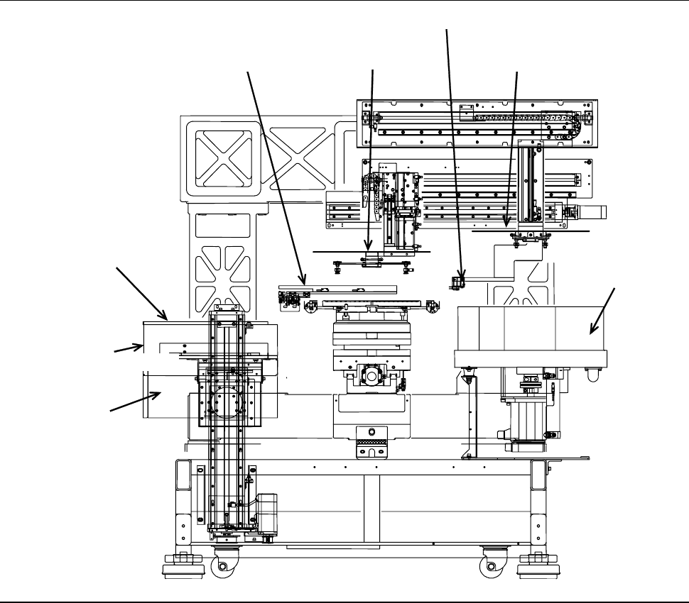
Axis arrangement (Continued)
Upper arm section
Spinner section
Lower arm section
Push-pull arm section
Cassette stage
Elevator section
Frame centering section
Inspection Workpiece Door
A-11
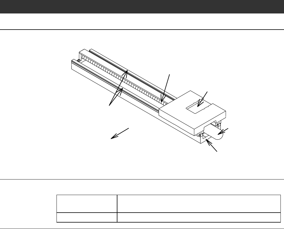
2-2. X-axis Section
X-axis section component names
The X-axis section consists of the following components.
AC servomotor
Linear guide
Ball-bearing leadscrew
X-axis slider
Front
X-axis base
X-axis drive section mechanism
The X-axis drive section is structured as follows:
Driving source Driven by an AC servomotor with the aid of the ball-
bearing leadscrew.
Slide mechanism Employs a linear guide to assure smooth linear motion.