DFD6361-Maintenance.pdf - 第27页
A-11 2-2. X-axis S ection X-axis sectio n com ponent names The X-axis section consists of the following components. AC serv omotor Linear gu ide Ball -beari ng le adscrew X-ax is slider Front X-ax is base X-ax is driv e …
A-10
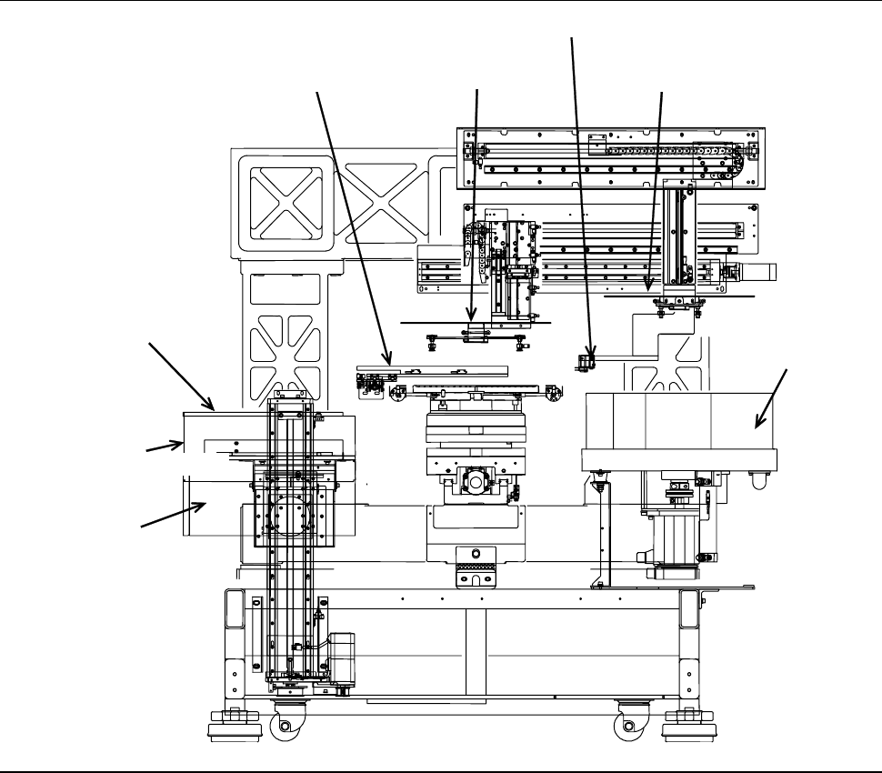
Axis arrangement (Continued)
Upper arm section
Spinner section
Lower arm section
Push-pull arm section
Cassette stage
Elevator section
Frame centering section
Inspection Workpiece Door
A-11
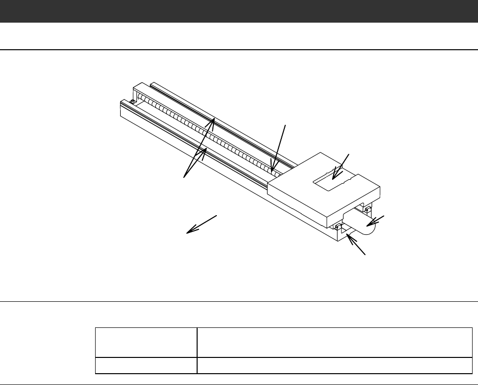
2-2. X-axis Section
X-axis section component names
The X-axis section consists of the following components.
AC servomotor
Linear guide
Ball-bearing leadscrew
X-axis slider
Front
X-axis base
X-axis drive section mechanism
The X-axis drive section is structured as follows:
Driving source Driven by an AC servomotor with the aid of the ball-
bearing leadscrew.
Slide mechanism Employs a linear guide to assure smooth linear motion.
A-12
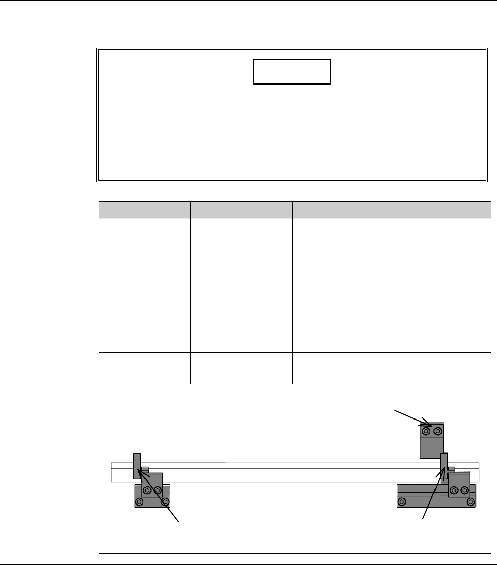
X-axis position detection section
In order to detect the X-axis position, photointerrupters (sensor) are installed
at the right and left stroke end limit.
NOTICE
The machine uses photointerrupters to detect an axis position.
The photointerrupter provides the reference for the axis origin
position. If the axis origin is displaced from its proper position, this
may lead to a failure of the machine. Therefore, if any associated
parts need to be replaced, contact your nearest DISCO Service
Office.
Sensor Name Sensor Position Operation
Right-end
sensor
Rightward stroke
end limit
- Provides the reference position for
initialization, setup, cutting and
alignment operations.
- Detects the right end limit of the X-
axis maximum stroke.
- The reference (origin) position is
located at 9.5mm left of right soft-
end, which is fixed at 0.5mm left of
the right-end sensor.
Left-end sensor Leftward stroke
end limit
- Detects the left end limit of the X-
axis maximum stroke.
Left-end sensor
Right-end sensor
Slit plate