DFD6361-Maintenance.pdf - 第31页
A-15 Y-axi s position detec tion section ( Continued) [Y1-ax is rear end] Slit p late Y1-axis rear end s ensor [Y2-ax is front e nd] Slit p late Y2-axis f ront end sens or [Y1-Y 2 axis approach end] Slit p late Y1-Y2 axi…
A-14
Y-axis position detection section
For Y-axis position detection, photointerrupters (sensor) are installed at the Y-
axis origin and front and rear stroke end limit.
NOTICE
The machine uses photointerrupters to detect an axis position.
The photointerrupter provides the reference for the axis origin
position. If the axis origin is displaced from its proper position, this
may lead to a failure of the machine. Therefore, if any associated
parts need to be replaced, contact your nearest DISCO Service
Office.
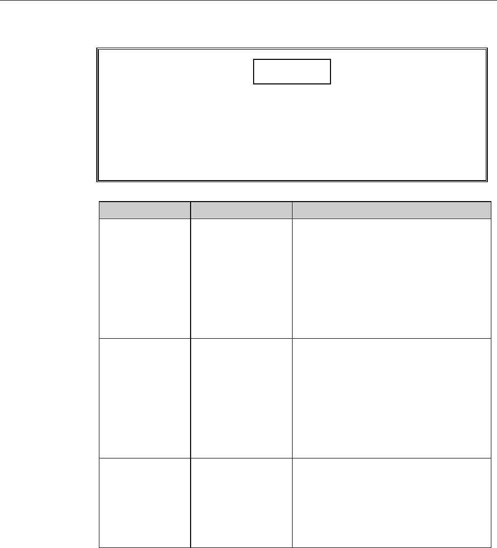
Sensor Name Sensor Position Operation
Rear end sensor Rear stroke end
limit
- Provides the reference position for
initialization, setup, cutting and
alignment operations of Y1-axis.
- The Y1-axis reference (origin)
position is located 20mm front from
the rear end sensor.
- Detects the rear end limit of the Y1-
axis maximum stroke.
Front end sensor Front stroke end
limit
- Provides the reference position for
initialization, setup, cutting and
alignment operations of Y2-axis.
- The Y2-axis reference (origin)
position is located 20mm rear from
the front-end sensor.
- Detects the front-end limit of the
Y2-axis maximum stroke.
Approach end
sensor
A sensor located
at Y1-axis front
end and a slit plate
at Y2-axis back
end, which are
used in a pair.
- Prevents collision between Y1- and
Y2-axis.
- Detects the approach threshold value
(30mm), which is the distance
between the blade center of spindle1
and spindle2.
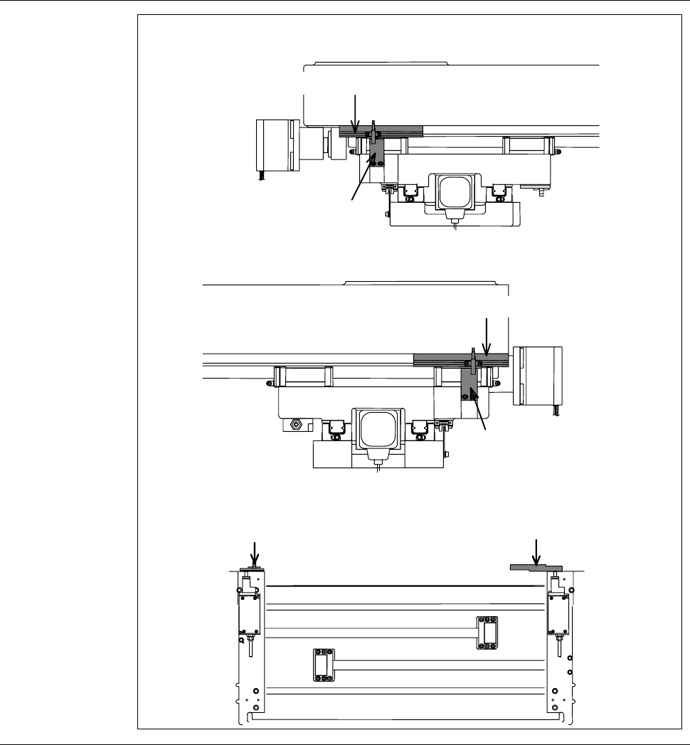
A-15
Y-axis position detection section (Continued)
[Y1-axis rear end]
Slit plate
Y1-axis rear end sensor
[Y2-axis front end]
Slit plate
Y2-axis front end sensor
[Y1-Y2 axis approach end]
Slit plate
Y1-Y2 axis approach end sensor
A-16
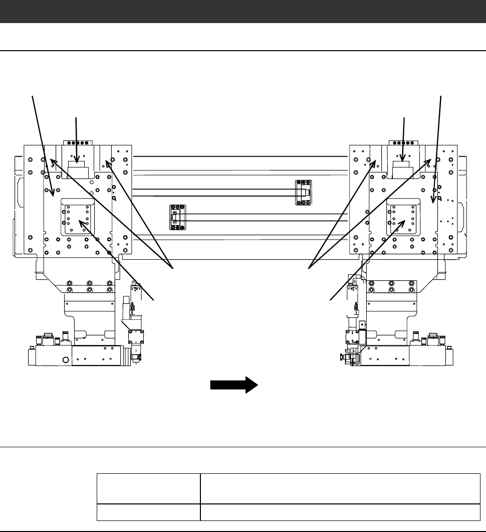
2-4. Z (Z1 and Z2)-axis Section
Z-axis section component names
The Z-axis section consists of the following components.
FRONT
Z2-axis stepping motor
Linear guide
Z2-axis slider
Z1-axis stepping motor
Z1-axis slider
Linear guide
Ball-bearing leadscrew Ball-bearing leadscrew
Z-axis drive section mechanism
The Z-axis drive section is structured as follows:
Driving source Driven by the stepping motor with the aid of the ball-
bearing leadscrew.
Slide mechanism Employs a linear guide to assure smooth linear motion.