DFD6361-Maintenance.pdf - 第447页
E-11 Procedur es for cleani ng the non-con tact setup sens or wi th abrasives ( Continued) Step No. Do This 5 Scrub the detec tion surface with the cotton swa b having abrasives a few times. ÿ Detectio n surface Front 6 …
E-10
1-1-3. Cleaning the non-contact setup sensor with abrasives
[Optional accessory]
Before cleaning
Have on hand the following items for cleaning the non-contact setup sensor
using abrasives.
Abrasives [optional accessory] (Part No AKFEF-PA)
Cotton swab
Procedures for cleaning the non-contact setup sensor with abrasives
CAUTION
Do not apply the abrasives to the area other than the detection
surface.
If you use the abrasives to the area other than the detection surface,
adhesive come off and the non-contact setup sensor may be
damaged.
NOTICE
Do not use the abrasives other than the one designated by Disco.
Otherwise, the non-contact setup sensor may be damaged.
Step No.
Do This
(Continued from the previous section)
1
Verify that the protecting water from the non-contact setup block
stops.
- If not;
Press <F1> button to stop the protecting water.
2
Verify that air at the non-contact setup sensor section stops.
- If not;
Press <F2> button to stop air.
3
Moisten the cotton swab with water.
4
Apply the abrasives on the moistened cotton swab.

E-11
Procedures for cleaning the non-contact setup sensor with abrasives (Continued)
Step No.
Do This
5
Scrub the detection surface with the cotton swab having abrasives
a few times.
ÿ
Detection surface
Front
6
Press the <F1> button to turn ON the protecting water.
7
Using the new cotton swab having no abrasives, rinse the abrasives
on the detection surface.
8
Press the <F1> button to turn OFF the protecting water.
9
Press the <F2> button to turn ON air.
10
After cleaning, check whether the voltage level reading on the
NCS SENSOR CLEANING screen is within a range of 100 ± 2%
(4.90 to 5.10 V).
- If not;
Repeat cleaning of step No. 1 through 9 of this table.
- When the voltage level does not come within this range, even
after repeating cleaning;
Adjust the non-contact setup amplifier.
See the section 1-1-4 of this chapter, [Adjusting the non-contact
setup amplifier].
Continued in the next section.
E-12
1-1-4. Adjusting the non-contact setup amplifier
The case where this procedure is required
Adjusting the non-contact setup amplifier is required when the voltage level
reading on the NCS SENSOR CLEANING screen comes outside the range of
100 ± 2% (4.90 to 5.10 V), even after repeated cleaning.
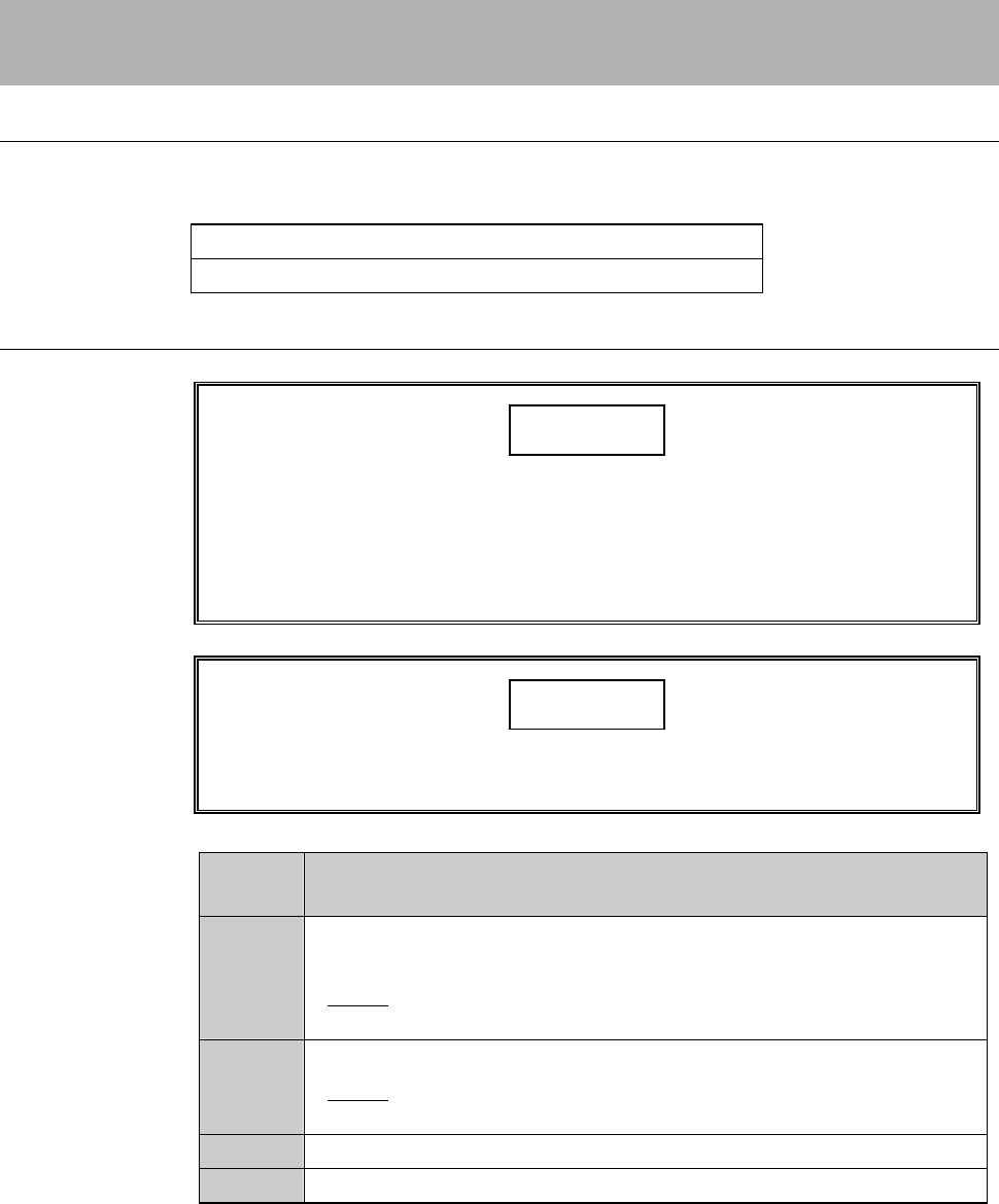
Tools
Have on hand the following tool.
Tool Part No.
Amplifier adjustment driver AK81526287
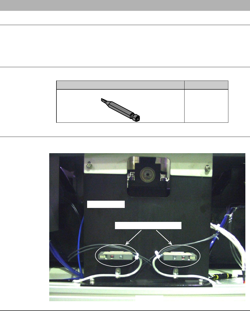
Position of the non-contact setup amplifier
The illustration below shows the location of the non-contact setup amplifier.
LEFT SIDE
Main body base
Non-contact setup amplifier