DFD6361-Maintenance.pdf - 第451页
E-15 Procedur e for adjus ting the n on-contact s etup ampli fier (Conti nued) Step No. Do This 4 Turn the sensitivity regulation dial of the amplifier with the amplifier adjustme nt driver so that the voltage level read…
E-14
Procedure for adjusting the non-contact setup amplifier (Continued)
Step No. Do This
(Continued from the previous section)
1
Make sure that NCS SENSOR CLEANING screen [screen 4.8] is
displayed.
- When it is not ;
See the section 1-1-1 of this chapter, [Calling up the NCS
SENSOR CLEANING screen [screen 4.8]].
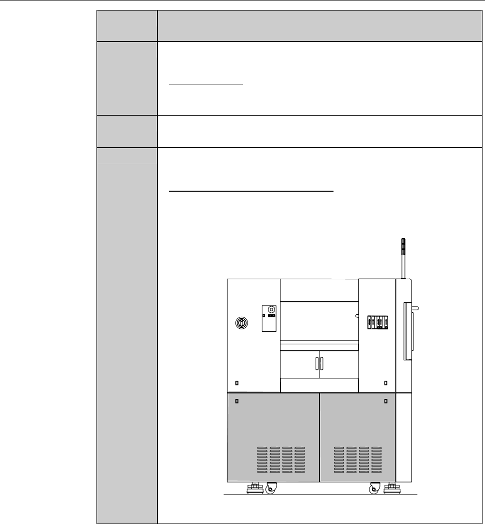
2
Open the splash cover.
- The interlock system is actuated.
3
Remove the cover [H] and [I]. Then store it sufficiently away
from the working area.
- For the cover removal procedures,
see the section B-2-1, [Removing the Machine Outer Cover
and Status Indicator] of Installation Manual.
ÿ
LEFT SIDE
[H] [I]
E-15
Procedure for adjusting the non-contact setup amplifier (Continued)
Step No. Do This
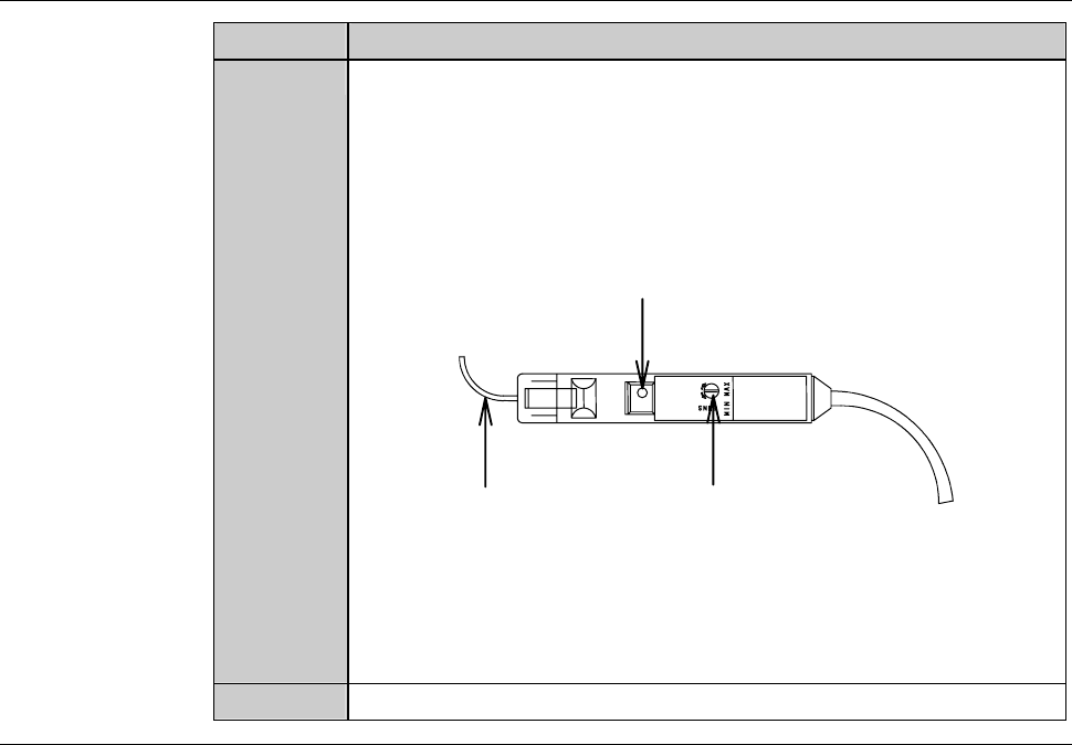
4
Turn the sensitivity regulation dial of the amplifier with the
amplifier adjustment driver so that the voltage level reading on
the NCS SENSOR CLEANING screen [screen 4.8] comes within
a range of 100 ± 2% (4.90 to 5.10 V).
- Turn the sensitivity regulation dial clockwise to increase the
sensitivity.
Fiber
Sensitivity reguration dial
Power indication lamp
- If the sensor voltage level does not come within the range of
100 ± 2% (4.90 to 5.10 V) even after setting the sensitivity
regulation dial at MAX, the fiber may be bent or the amplifier is
broken down.
In such cases, contact your nearest DISCO office.
5
Reinstall the cover [H] and [I].
Continued in the next section.
E-16
1-1-5. Completion of cleaning the non-contact setup sensor
Procedures for completion of cleaning the non-contact setup sensor
Step No. Do This
(Continued from the previous section)
1
Close the splash cover.
2
Press the <System Initial> button to effect system initialization.
3
Press the <Spindle> button to rotate the spindle.
4
Press the <Cut Water> button to turn ON the wheel coolant water
supply.
5
Idle the machine for 10 minutes.
6
Carry out the sensor calibration setup.
- For the procedures of the sensor calibration setup,
see B-7, [Setup] of Operation manual.
If errors or height variations frequently occur
If setup-related errors or height variations frequently occur immediately after
setup, even after repeating to clean the sensor detection surface or adjusting
the amplifier, the problem is attributable to a bent fiber or defective amplifier.
When this type of trouble occurs, contact your nearest DISCO office.
The following setup-related errors might occur.
Error No. Error Message
B0023 Spindle continuity error.
B0582 Z1-axis calibrate sensor.
B0583 Z1-axis setup error (error detection).
B0584 Z1-axis setup error (Z-axis position error).
B0585 Z1-axis setup error (no detection).
B0586 Z1-axis non-contact setup reappearance error.
B0587 Z1-axis blade wear check error.
B0589 Z2-axis calibrate sensor.
B0590 Z2-axis setup error (error detection).
B0591 Z2-axis setup error (Z-axis position error).
B0592 Z2-axis setup error (no detection).
B0593 Z2-axis non-contact setup reappearance error.
B0594 Z2-axis blade wear check error.
B1133 Non-Contact setup check error. (Z1)
B1134 Non-Contact setup check error. (Z2)