DFD6361-Maintenance.pdf - 第452页
E-16 1-1-5. Com pletion of cleani ng the non-c ontact setup sensor Procedur es for c ompleti on of clea ning th e non- contact set up sens or Step No. Do This (Continued from the previous section) 1 Close the splash cove…
E-15
Procedure for adjusting the non-contact setup amplifier (Continued)
Step No. Do This
4
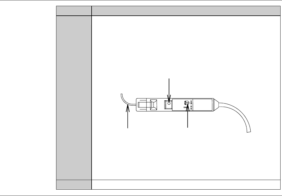
Turn the sensitivity regulation dial of the amplifier with the
amplifier adjustment driver so that the voltage level reading on
the NCS SENSOR CLEANING screen [screen 4.8] comes within
a range of 100 ± 2% (4.90 to 5.10 V).
- Turn the sensitivity regulation dial clockwise to increase the
sensitivity.
Fiber
Sensitivity reguration dial
Power indication lamp
- If the sensor voltage level does not come within the range of
100 ± 2% (4.90 to 5.10 V) even after setting the sensitivity
regulation dial at MAX, the fiber may be bent or the amplifier is
broken down.
In such cases, contact your nearest DISCO office.
5
Reinstall the cover [H] and [I].
Continued in the next section.
E-16
1-1-5. Completion of cleaning the non-contact setup sensor
Procedures for completion of cleaning the non-contact setup sensor
Step No. Do This
(Continued from the previous section)
1
Close the splash cover.
2
Press the <System Initial> button to effect system initialization.
3
Press the <Spindle> button to rotate the spindle.
4
Press the <Cut Water> button to turn ON the wheel coolant water
supply.
5
Idle the machine for 10 minutes.
6
Carry out the sensor calibration setup.
- For the procedures of the sensor calibration setup,
see B-7, [Setup] of Operation manual.
If errors or height variations frequently occur
If setup-related errors or height variations frequently occur immediately after
setup, even after repeating to clean the sensor detection surface or adjusting
the amplifier, the problem is attributable to a bent fiber or defective amplifier.
When this type of trouble occurs, contact your nearest DISCO office.
The following setup-related errors might occur.
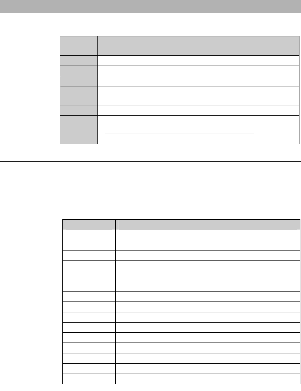
Error No. Error Message
B0023 Spindle continuity error.
B0582 Z1-axis calibrate sensor.
B0583 Z1-axis setup error (error detection).
B0584 Z1-axis setup error (Z-axis position error).
B0585 Z1-axis setup error (no detection).
B0586 Z1-axis non-contact setup reappearance error.
B0587 Z1-axis blade wear check error.
B0589 Z2-axis calibrate sensor.
B0590 Z2-axis setup error (error detection).
B0591 Z2-axis setup error (Z-axis position error).
B0592 Z2-axis setup error (no detection).
B0593 Z2-axis non-contact setup reappearance error.
B0594 Z2-axis blade wear check error.
B1133 Non-Contact setup check error. (Z1)
B1134 Non-Contact setup check error. (Z2)
E-17
1-2. Cleaning the Blade Breakage Detector Sensor
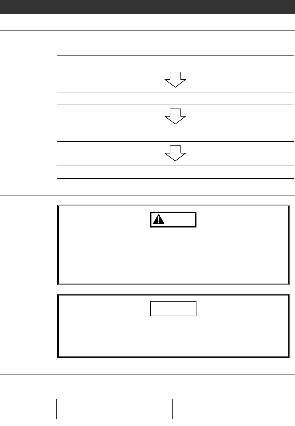
Operation flow
The procedure for cleaning the blade breakage detector sensor consists of the
following steps.
1-2-1 Removing the blade breakage detector
1-2-2 Cleaning the blade breakage detector sensor
1-2-3 Adjusting the amplifier of blade breakage detector
1-2-4 Completion of cleaning the blade breakage detector sensor
Safety items for cleaning the blade breakage detector sensor
WARNING
If any touch panel control is inadvertently activated during
maintenance or inspection, unexpected machine operation may
cause death or serious injury.
While you don't use the touch panel, press the Disco's logo button
located at the upper left of the screen in order to lock up and
deactivate the touch panel.
NOTICE
Neither safety goggles, protective gloves, stepstools, flashlights nor
alcohol, all of which are necessary for maintenance work, are not
supplied with the machine. Use what are furnished in your factory or
what comply with your factory's standards.
Before cleaning
Have on hand the following items for cleaning the blade breakage detector
sensor.
Cotton swab (or soft cloth)
Alcohol