DFD6361-Maintenance.pdf - 第462页
E-26 1-2-3-1. Moving the Y (Y1, Y2)-a xis Procedur es for mov ing the Y (Y 1, Y2)- axis Step No. Do This (Continued from the previous section) 1 With the button, move the Y1-axis to the center. 2 From the ENGINEERING MA …
E-25
Safety items for adjusting the amplifier of blade breakage detector
WARNING
- This procedure requires you to put your hand into the drive section,
where your hand or fingers could be caught or cut off.
During this operation, allow no one else to touch the machine.
- If you keep the splash cover closed after moving the axes, you have
to perform the adjustment operation with the interlock system
released. Since there is a driving section near your working section,
if the interlock system is canceled, your hands or arms may be
caught or amputated due to unexpected machine operation.
After you move the axes, be sure to open the splash cover in order
to activate the interlock of the cover.
CAUTION
When you perform maintenance with the partition removed, observe
the following precaution. If you stand the removed partition against
the machine, you may receive injury by the partition if it is toppled by
the earthquake or like that.
After taking off the partition for maintenance purposes, store it
sufficiently away from the working area.
CAUTION
If you don't use the amplifier adjustment driver designed specifically
for this use when you turn the sensitivity regulation dial, the dial may
be damaged or broken.
Ensure to use the amplifier adjustment driver (black resin).
E-26
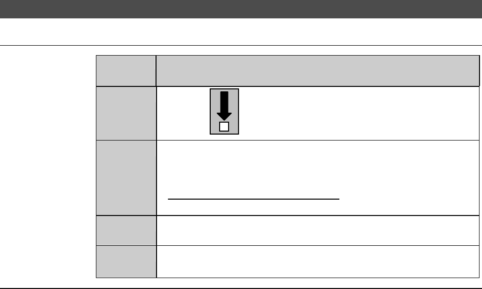
1-2-3-1. Moving the Y (Y1, Y2)-axis
Procedures for moving the Y (Y1, Y2)-axis
Step No.
Do This
(Continued from the previous section)
1
With the button, move the Y1-axis to the center.
2
From the ENGINEERING MAINTENANCE screen [screen 7.0],
press the <F2> button.
- The AXIS OPERATION screen then appears.
- For the AXIS OPERATION screen,
see the section C-3, [Axis Operation Check].
3
From the AXIS OPERATION screen, move the Y2-axis to the
center.
4
Open the splash cover.
- The interlock system is actuated.
Continued in the next section.
E-27
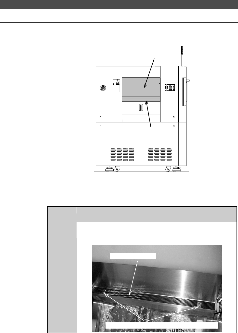
1-2-3-2. Removing the partition (left)
Position of the partition (left)
The illustration below shows the location of the partition (left).
ÿ
LEFT SIDE
Partition (left)
Safety switch cover
Procedures for removing the partition (left)
Step No.
Do This
(Continued from the previous section)
1
Make sure that the drive sections are stopped.
2
Loosen and remove the mounting screws of the safety switch
cover.
Safety switch cover
Mounting screws (the cross-shaped recess screw)