DFD6361-Maintenance.pdf - 第463页
E-27 1-2-3-2. Removing the partition (left) Position of the partition (left) The illustration below shows the loca tion of the partition (left). ÿ LEFT SIDE Partitio n (left) S afety s wi tch cov er Procedur es for rem o…
E-26
1-2-3-1. Moving the Y (Y1, Y2)-axis
Procedures for moving the Y (Y1, Y2)-axis
Step No.
Do This
(Continued from the previous section)
1
With the button, move the Y1-axis to the center.
2
From the ENGINEERING MAINTENANCE screen [screen 7.0],
press the <F2> button.
- The AXIS OPERATION screen then appears.
- For the AXIS OPERATION screen,
see the section C-3, [Axis Operation Check].
3
From the AXIS OPERATION screen, move the Y2-axis to the
center.
4
Open the splash cover.
- The interlock system is actuated.
Continued in the next section.
E-27
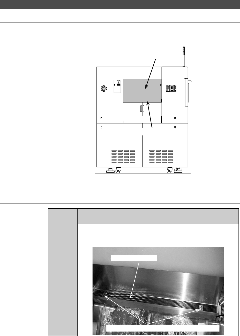
1-2-3-2. Removing the partition (left)
Position of the partition (left)
The illustration below shows the location of the partition (left).
ÿ
LEFT SIDE
Partition (left)
Safety switch cover
Procedures for removing the partition (left)
Step No.
Do This
(Continued from the previous section)
1
Make sure that the drive sections are stopped.
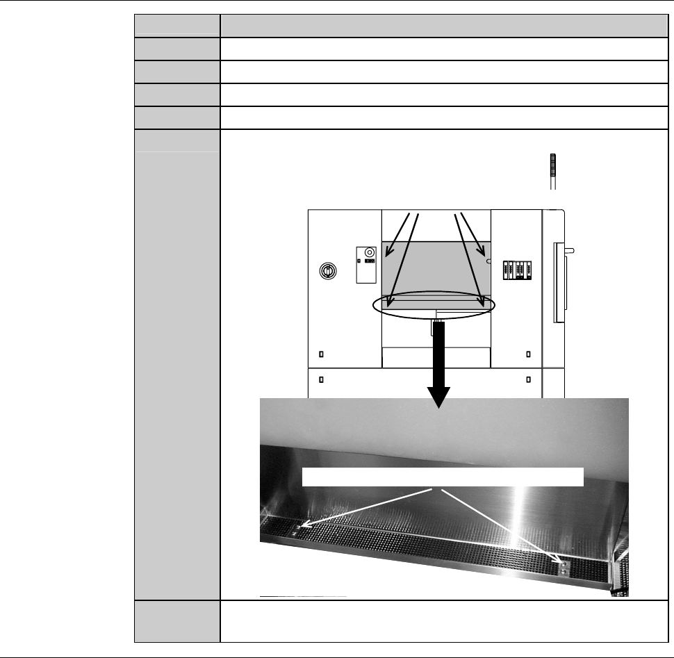
2
Loosen and remove the mounting screws of the safety switch
cover.
Safety switch cover
Mounting screws (the cross-shaped recess screw)
E-28
Procedures for removing the partition (left) (Continued)
Step No.
Do This
3
Lift the safety switch cover approximately by 10mm.
4
Move the safety switch cover to its either side.
5
Pull the safety switch cover toward you and remove it.
6
An assistant holds the partition.
7
Remove the mounting screws of the partition.
Mounting screw (cross-shaped recess screw)
Mounting screw (cross-shaped recess screw)
8
Remove the partition. Store it sufficiently away from the
working area.
Continued in the next section.