DFD6361-Maintenance.pdf - 第510页
E-74 5-4-6. Com pletion of cleani ng the spindle 2 cool ant water path Procedur es for compl etion of cl eaning th e spindle 2 coolant w ater path W ARNING If you op erate the machine w hile its i nterior i s wet wi th w…
E-73
5-4-5. Cleaning the spindle 2 coolant water path
Procedures for cleaning the spindle 2 coolant water path
Step No. Do This
(Continued from the previous section)
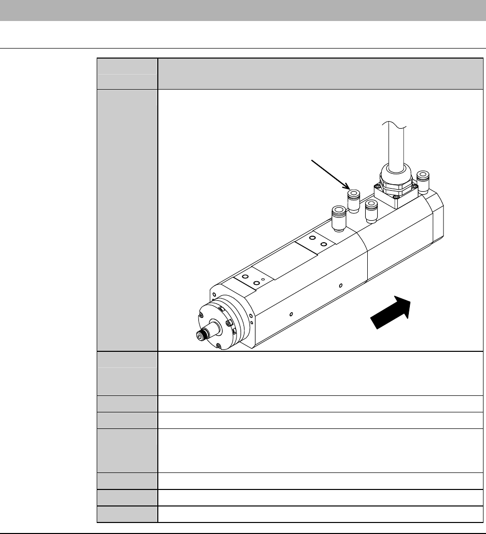
1
Disconnect the tube from the spindle 2 coolant water IN port
(inlet).
ÿ
Front
Spindle coolant water inlet
2
Connect the deionized watercourse to the spindle 2 coolant water
IN port (inlet), and then flow the deionized water for a period of
one minute.
3
Close the deionized watercourse main valve.
4
Disconnect the deionized watercourse from the IN port.
5
Make an air supply connection to the spindle 2 coolant IN port
(inlet) and blow air into the coolant path for one minute.
[Air pressure: 290 kPa (3.0 kgf/cm
2
)orlower]
6
Close the main air supply valve.
7
Disconnect the air tube.
8
Repeat the steps 2 through 7 at least three times.
Continued in the next section.
E-74
5-4-6. Completion of cleaning
the spindle 2 coolant water path
Procedures for completion of cleaning the spindle 2 coolant water path
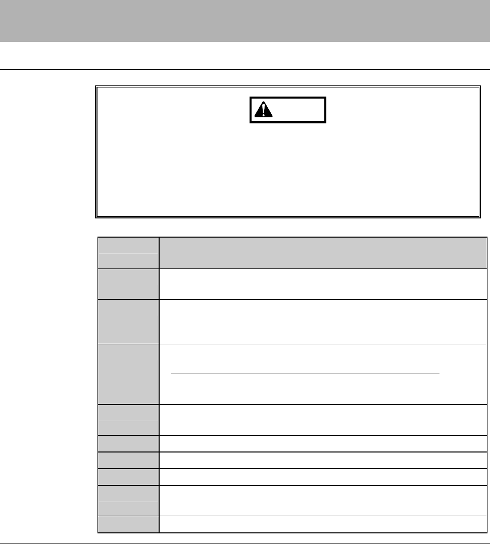
WARNING
If you operate the machine while its interior is wet with water, you
may receive electric shock that could result in serious injury or death.
If the machine is wet with water, do not turn ON the facility power
supply until it dries.
If the floor is wet with water, turn OFF the facility power supply and
wipe the floor dry.
Step No. Do This
(Continued from the previous section)
1
Connect the tube firmly at the spindle 2 coolant water IN port
(inlet).
2
Open the spindle 2 coolant water supply main valve and make
sure that there are no water leaks at the joint section of the
spindle coolant water IN port (inlet).
3
Reinstall the roll cover of the spindle 2 axis tail section.
- For the Y-axis section roll cover installation procedure;
See the section F-1-8, [Replacing the Y-axis Section Roll
Cover].
4
Close the cover [P], and then tighten the retaining screw of the
cover.
5
Reinstall the cover [A].
6
Open the facility air supply main valve.
7
Turn ON the facility power source.
8
Open the circuit breaker lever lockout and turn ON the circuit
breaker.
9
Insert the key into the main switch and turn ON the main switch.
E-75
6. Maintenance to Be Performed at 365-Day
(Recommended) Intervals
Summary of this section
This section describes the maintenance to be done at 365-day intervals.
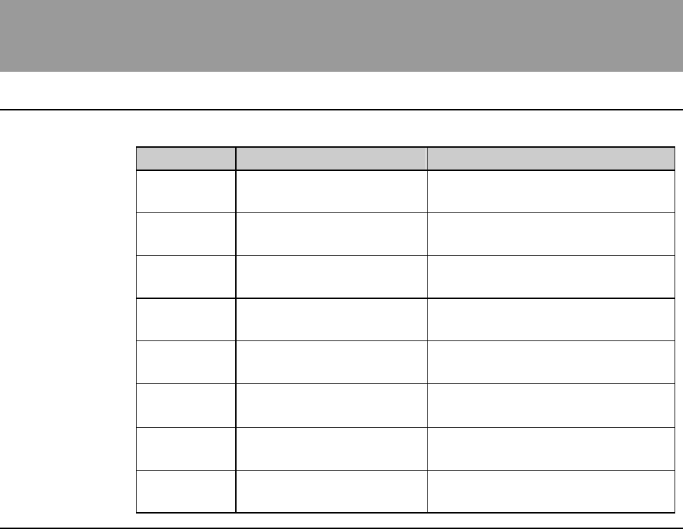
Section No. Title Contents
6-1 Cleaning the Vacuum
Ejector
- Procedures for cleaning the
vacuum ejector
6-2 Greasing the X-axis - Procedures for greasing the X-
axis
6-3 Greasing the push-pull
axis
- Procedures for greasing the
push-pull axis
6-4 Greasing the upper arm
axis
- Procedures for greasing the
upper arm axis
6-5 Greasing the lower arm
axis
- Procedures for greasing the
lower arm axis
6-6
Greasing the θ-axis sensor
assembly section
- Procedures for greasing the θ-
axis sensor assembly section
6-7 Greasing the Y-axis - Procedures for greasing the Y-
axis
6-8 Greasing the Z-axis - Procedures for greasing the Z-
axis