DFD6361-Maintenance.pdf - 第514页
E-78 Procedur es for cl eanin g the vacuu m ejector ( Continued) Step No. Do This 6 (Continue d) V P E Blow air to clean Air OU T Air IN Non returned valve (Only MOEGH020) Part Nam e Manuf acturer Part No. Usage MOEGH020…
E-77
Procedures for cleaning the vacuum ejector (Continued)
Step No. Do This
3
Shut off the facility power supply.
4
Close the facility main valve of air.
5
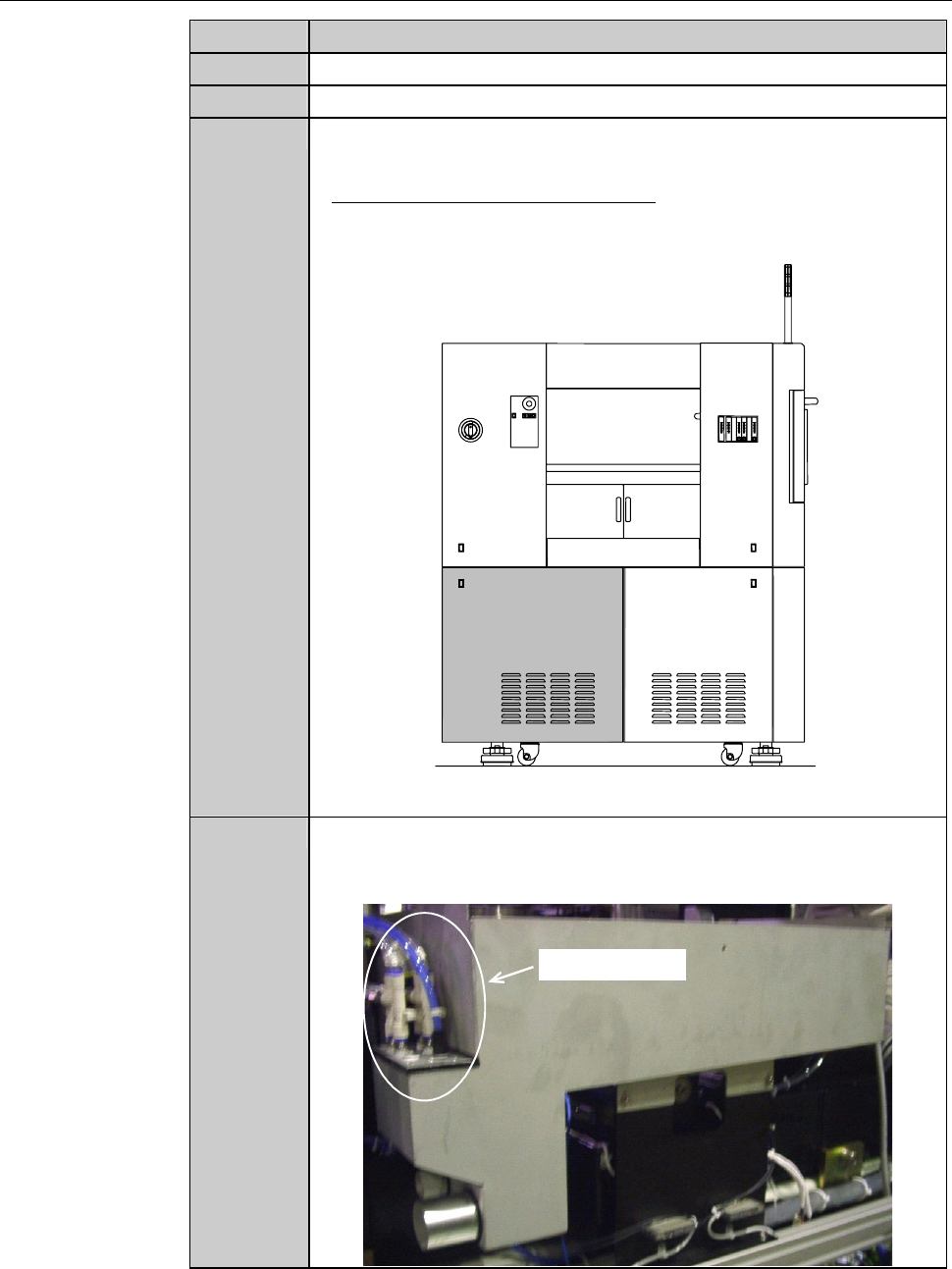
Remove the cover [H]. Then store it sufficiently away from the
working area.
- For the cover removal procedures;
See the section B-2-2, [Removing the Machine Outer Cover
and Status Indicator] of Installation Manual.
ÿ
[H]
LEFT SIDE
6
Disconnect the vacuum ejector and its piping as an assembly.
Then blow the inside of the vacuum ejector by air at the location
where water drip does not adhere on the machine.
Vacuum ejector
E-78
Procedures for cleaning the vacuum ejector (Continued)
Step No. Do This
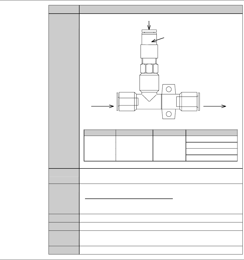
6
(Continued)
V
P
E
Blow air to clean
Air OUTAir IN
Non returned valve
(Only MOEGH020)
Part Name Manufacturer Part No. Usage
MOEGH020 For chuck table
Forspinnertable
For lower arm
Ejector SMC
For upper arm
7
Reinstall the vacuum ejector and its piping to their original
positions.
8
Reinstall the cover [H] in its original position.
- For the cover installation procedure;
See the section B-1-6, [Mounting Machine Outer Covers] of
Installation Manual.
9
Turn ON the facility power source.
10
Open the facility main valve of air.
11
Open the circuit breaker lever lockout and then turn ON the
circuit breaker.
12
Insert the key into the main switch and turn ON the main switch.
E-79
6-2. Greasing the X-axis
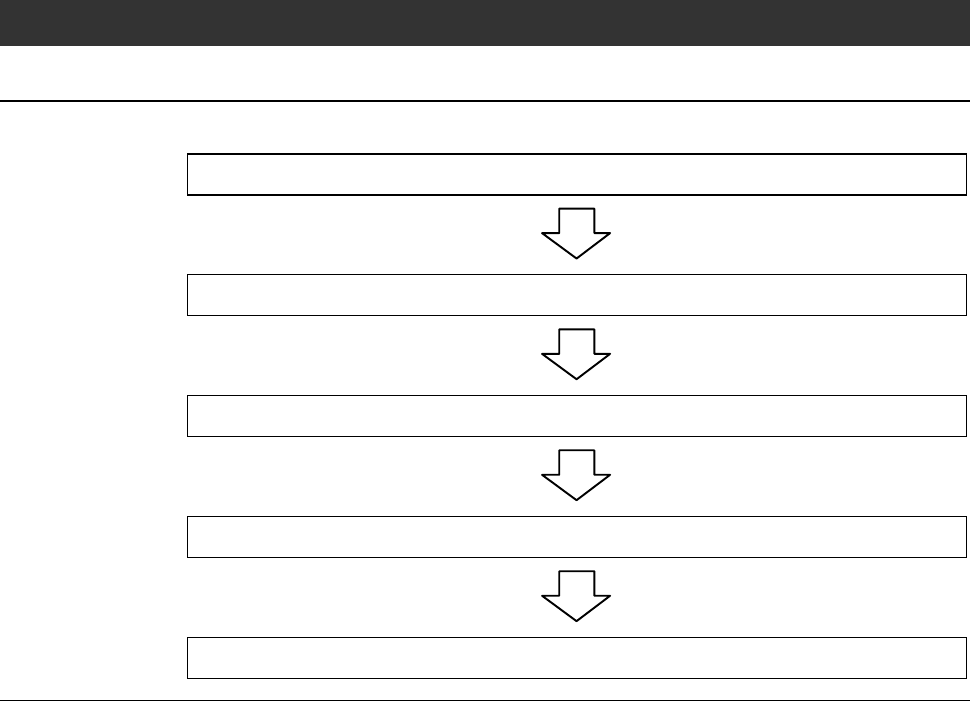
Operation flow
The procedure for greasing the X-axis consists of the following steps.
6-2-1 Preparation of greasing the X-axis
6-2-2 Cleaning the right-hand X-axis and its periphery
6-2-3 Cleaning the left-hand X-axis and its periphery
6-2-4 Greasing the X-axis
6-2-5 Completion of greasing the X-axis