DFD6361-Maintenance.pdf - 第532页
E-96 6-3-3. Com pletion of greasi ng the push-p ull axis Procedures for com pletion of gr easing the pu sh-pull axis Step No. Do Th is (Continued from the previous section) 1 Turn ON the facility power source. 2 Open the…
E-95
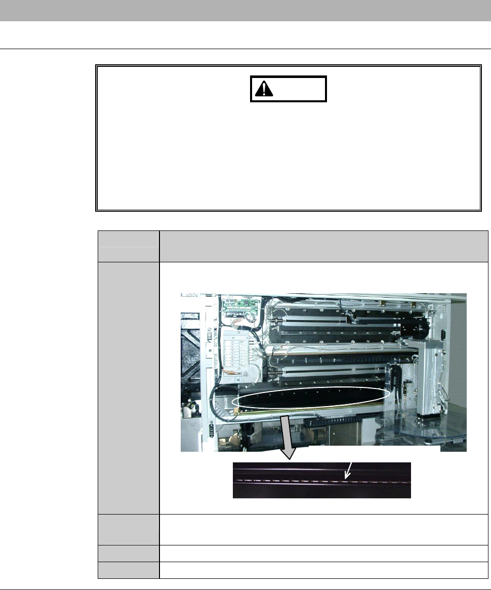
6-3-2. Greasing the push-pull axis
Procedures for greasing the push-pull axis
WARNING
When you perform the procedure set forth in this section, you have to
place your hands in a drive section. If you perform maintenance with
the power ON, your fingers or hands may be caught or cut off.
Turn OFF the machine and shut off the facility power supply before
starting this procedure.
Also, ensure that no other person touches the machine during
lubricating.
Step No. Do This
(Continued from the previous section)
1
With a lint-free cloth, wipe off the dirty grease on the rail and
ball-bearing leadscrew of the push-pull axis linear guide section.
Ball-bearing leadscrew
2
With a spatula, apply grease to the rail and ball-bearing
leadscrew.
3
Reinstall the lower transfer axis cover.
4
Close the front arm section cover.
Continued in the next section.

E-96
6-3-3. Completion of greasing the push-pull axis
Procedures for completion of greasing the push-pull axis
Step No. Do This
(Continued from the previous section)
1
Turn ON the facility power source.
2
Open the circuit breaker lever lockout and then turn ON the
circuit breaker.
3
Insert the key into the main switch and then turn ON the main
switch.
4
Press the <System Initial> button to effect system initialization.
5
On the AXIS OPERATION [screen 7.2], shuttle the push-pull
axis between the front and rear end at least three times to apply
the grease uniformly to the entire axis.
E-97
6-4. Greasing the Upper Arm Axis
Operation flow
The procedure for greasing the rail of upper arm axis linear guide section
consists of the following steps.
6-4-1 Preparation of greasing the upper arm axis
6-4-2 Greasing the upper arm axis
6-4-3 Completion of greasing the upper arm axis
Safety items for greasing the upper arm axis
WARNING
- In the digital I/O check procedures, any touch panel buttons other
than function buttons are inoperative.
Even if, for example, you press the <Cut Water> button, the wheel
coolant supply does not stop.
The personnel performing digital I/O checkout must bear this in
mind and exercise due care to ensure safety.
- In the digital I/O check procedures, the operation command for
solenoid valves and etc. can be forcibly turned ON and OFF, using
the function buttons. In some cases, therefore, a cylinder may be
invoked to operate.
Ensure that no person other than the maintenance personnel
touches the machine during this procedure.
- If any unexpected machine operation is inadvertently invoked, the
maintenance personnel may be injured.
While you don't use the touch panel, press the Disco's logo button
located at the upper left of the screen in order to lock up and
deactivate the touch panel.