DFD6361-Maintenance.pdf - 第54页
A-38 3. Main Body Section Main bo dy section c omponent names The main bod y section consists of the main bod y frame, main body base, electrical sy stem section, computer, drain port, duct port a nd utility connection s…
A-37
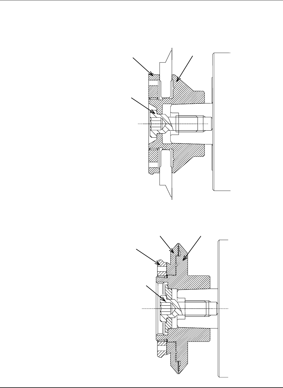
Installation diagram of hub mount/flange
Insert the hub mount or flange into the taper section at the edge of the spindle
axis.
[1.2kW spindle hub mount]
Hub mount
Hub Lock nut
Lock bolt
[Flange of 1.2 kW spindle flange (Washer type)]
Flange A
Flange B
Flange B lock nut
Lock bolt

A-38
3. Main Body Section
Main body section component names
The main body section consists of the main body frame, main body base,
electrical system section, computer, drain port, duct port and utility connection
section.
Part Features
Base section
Main body frame
Serves as the base for the main mechanism.
Provided with the mounts for level adjustment and
casters.
Electrical system
section
Contains the motor driver and controller. The electrical
system section can be easily pulled out because it is of a
slide type.
Computer Controls a man-machine interface. The computer can be
easily pulled out because it is of a slide type.
Drain port Collects drainage of the wheel and spindle coolant
water, and then discharges them out of the machine.
Duct port Collects exhaust air from the cutting chamber and
spinner section, and then discharges them out of the
machine.
Utility connection
section
Various solenoid valves are systematically arranged in
this section.
This section is equipped with inlets for water and air.
A-39
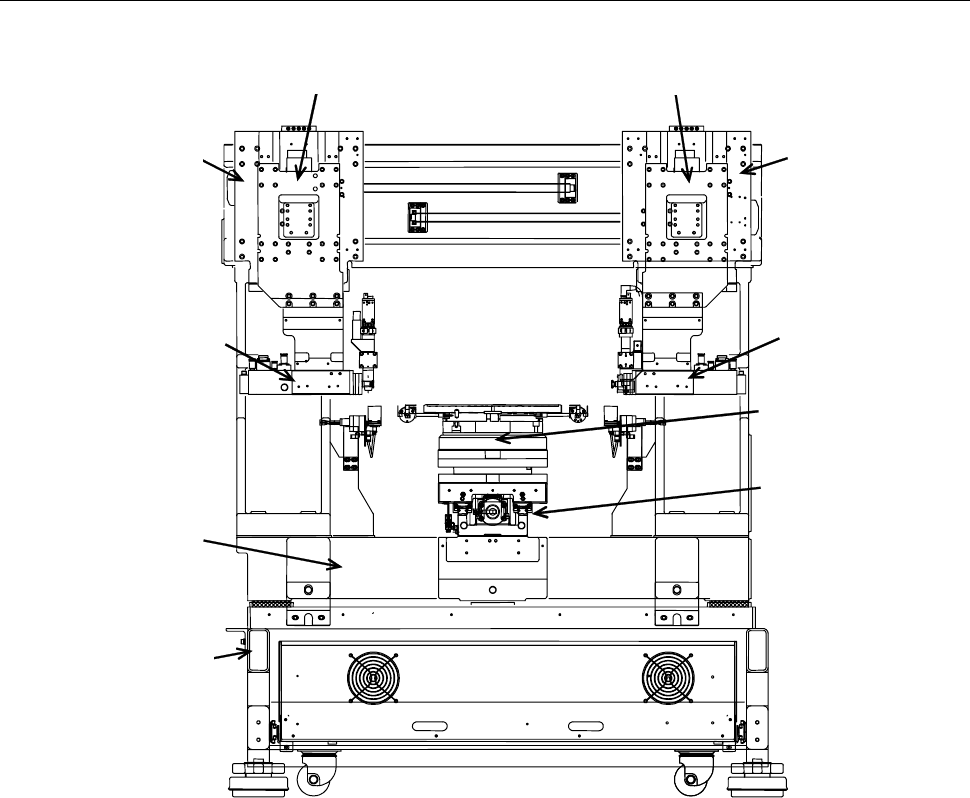
Main body section structural drawing
The structure of the main body section is shown below.
Z1-axis section
Y1-axis section
Z2-axis section
Y2-axis section
Main body frame
Spindle2-axis section
X-axis section
θ-axis section
Main body base
Spindle1-axis section