DFD6361-Maintenance.pdf - 第57页
A-41 Circui t breaker secti on structure The following drawings show the structure of the circuit brea ker section. [Standard speci fication] L1 L2 L3 PE [A] Leakage br eaker View from th e direction of [ A] PE term inal…
A-40
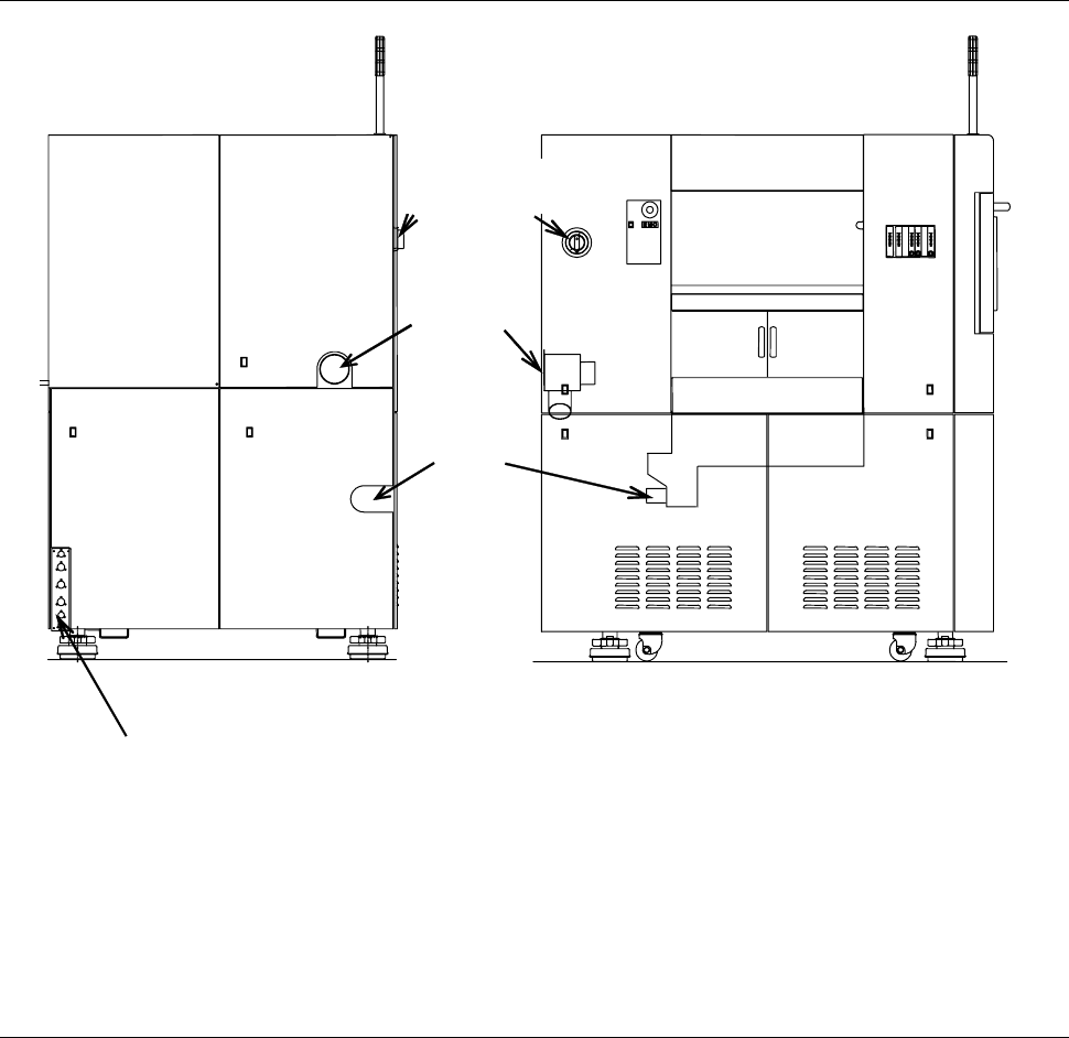
Main body section structural drawing (Continued)
Duct port
REAR SIDE LEFT SIDE
Drain port
Utility connection ports
- Rinse (Spinner cleaning water) [Optional accessory]
- Clean air
- Air
- Deionized water
- Spindle coolant water IN
- Spindle coolant water OUT
Circuit breaker
section
*) See the next page for the details of the circuit breaker section.
A-41
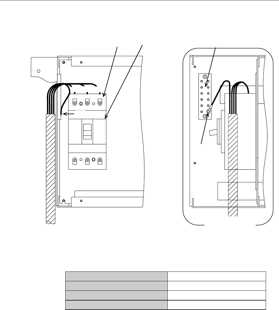
Circuit breaker section structure
The following drawings show the structure of the circuit breaker section.
[Standard specification]
L1 L2 L3
PE
[A]
Leakage breaker
View from the
direction of [A]
PE terminal bar
PE=Ground (GND)
Terminal board
[Power cable specifications]
Part number
XBEU04C3.50A
Part name
Cable (vinyl cabrite)
Nominal cross-sectional area
12AWG (equivalent to 3.5SQ)
Number of conductors
4
A-42
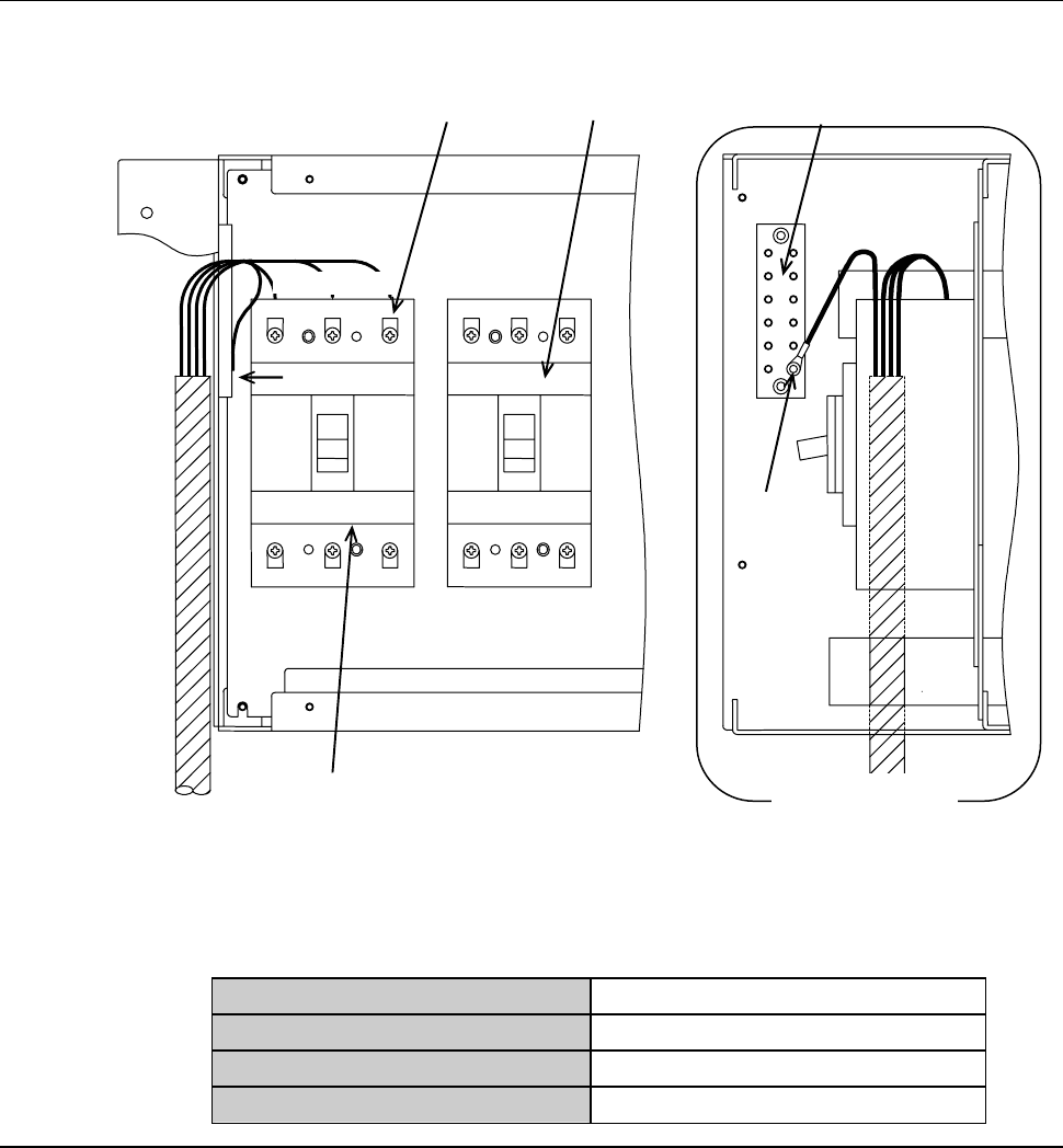
Circuit breaker section structure (Continued)
[Transformer specification (AC380 to 415V)]
PE
[A]
L1 L2 L3
PE terminal bar
Leakage breaker
Circuit breaker
PE=Ground (GND)
View from the
direction of [A]
Terminal board
[Power cable specifications]
Part number
XBEU04C3.50A
Part name
Cable (vinyl cabrite)
Nominal cross-sectional area
12AWG (equivalent to 3.5SQ)
Number of conductors
4