DFD6361-Maintenance.pdf - 第59页
A-43 Circui t breaker lev er structur e The circuit breaker lever must be placed in the "OFF" position, inserted into the notched se ction [A] and then secur ed together with the break er section cover. Break e…
A-42
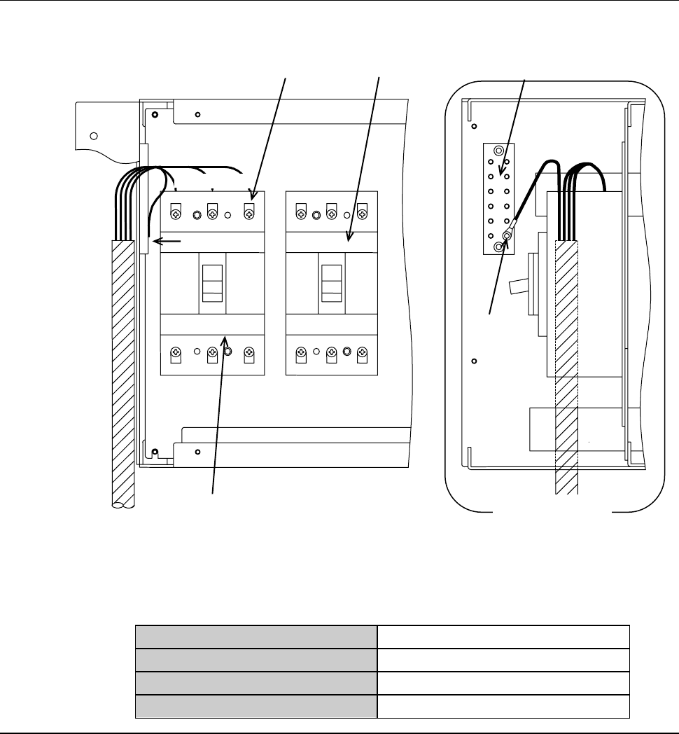
Circuit breaker section structure (Continued)
[Transformer specification (AC380 to 415V)]
PE
[A]
L1 L2 L3
PE terminal bar
Leakage breaker
Circuit breaker
PE=Ground (GND)
View from the
direction of [A]
Terminal board
[Power cable specifications]
Part number
XBEU04C3.50A
Part name
Cable (vinyl cabrite)
Nominal cross-sectional area
12AWG (equivalent to 3.5SQ)
Number of conductors
4
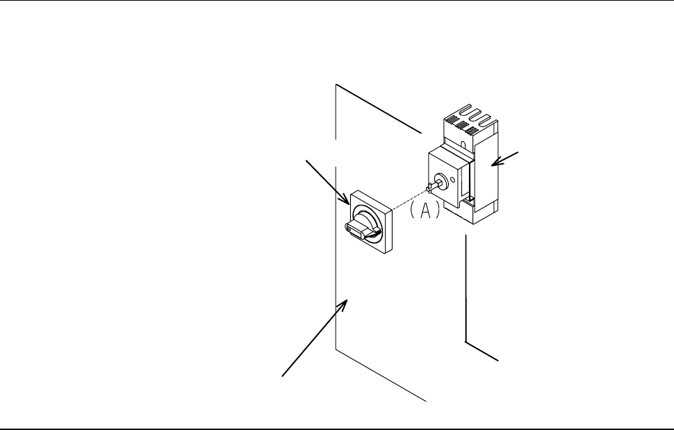
A-43
Circuit breaker lever structure
The circuit breaker lever must be placed in the "OFF" position, inserted into
the notched section [A] and then secured together with the breaker section
cover.
Breaker section cover
Breaker lever
Breaker
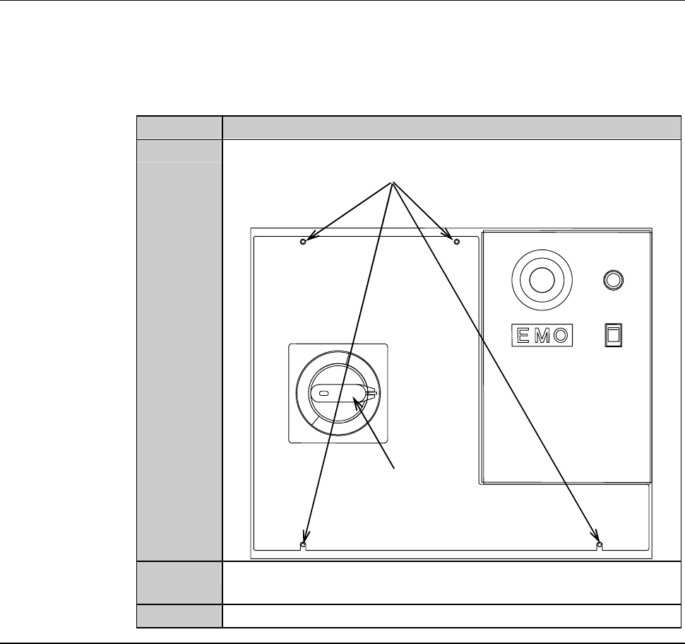
A-44
Circuit breaker section cover lock mechanism
When the breaker section outer cover is removed, the breaker section cover
shows up.
The circuit breaker section cover is locked by the circuit breaker lever and the
cover lock screws.
The procedures for releasing the cover lock are as follows:
Step No. Do This
1
Loosen the cover lock screw (M4).
Circuit breaker lever
Cover lock screw (M4)
2
Rotate the circuit breaker lever to "RESET" from "OFF" position
to unlock the lever lock.
3
Remove the breaker section cover.