DFD6361-Maintenance.pdf - 第591页
F-21 Procedur es for prep aration of re placing th e spindle 1 carbon brush (Continu ed) [ W hen ther e is no m aintenance s pace prov ided at the r ear side of the machine] (Continue d) Step No. Do This 8 Remove the pa …
F-20
Procedures for preparation of replacing the spindle 1 carbon brush (Continued)
[When there is no maintenance space provided at the rear side of the
machine]
CAUTION
When performing maintenance with the partition removed, observe
the following precaution. If you stand the removed partition against
the machine, you may receive injury by the partition if it is toppled by
the earthquake or like that.
When you take off the partition for maintenance purposes, store it
sufficiently away from the working area.
Step No. Do This
1
Press the <System Initial> button to effect system initialization.
2
From outside of the splash cover, visually make sure that the
spindle is completely stopped..
3
With the button, move the Y1-axis to its front end.
4
Open the internal facilities control cover at the front of the
machine. Turn OFF the main switch and then pull out the key.
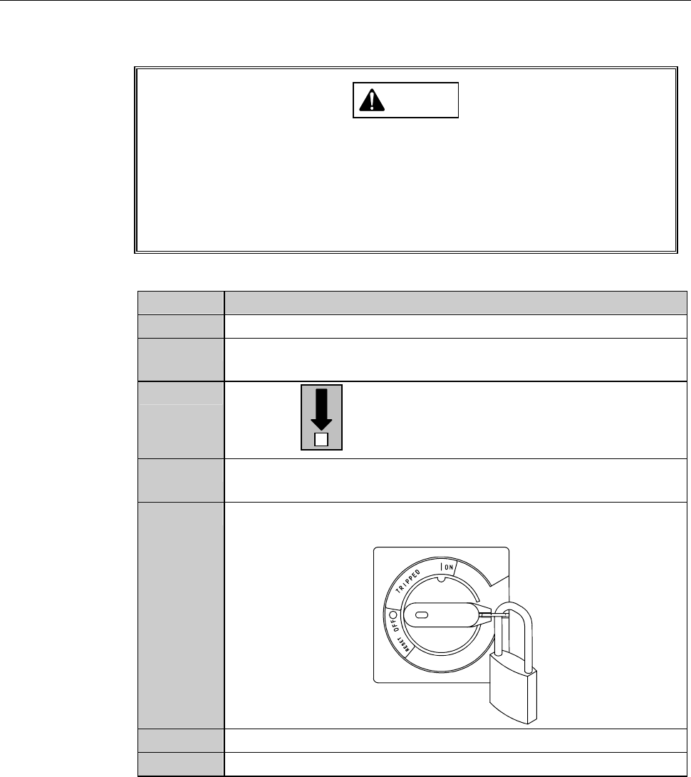
5
Turn OFF the circuit breaker at the left of the machine. Lock out
the circuit breaker lever with a padlock or the like.
6
Shut off the facility power supply.
7
Close the facility main valve of air.
F-21
Procedures for preparation of replacing the spindle 1 carbon brush (Continued)
[When there is no maintenance space provided at the rear side of the
machine] (Continued)
Step No. Do This
8
Remove the partition (left).
- For the removal procedures of the partition (left);
See the section E-1-2-3-2, [Removing the partition (left)].
9
Remove the bellows at the rear of the Y-axis.
- For the removal procedure of the bellows (for Y-axis);
See the section 3-5 of this chapter, [Replacing the Bellows (for
Y-Axis).
Continued in the next section.
F-22
1-4-1-2. Preparation of replacing the spindle 2 carbon brush
Procedures for preparation of replacing the spindle 2 carbon brush
Step No. Do This
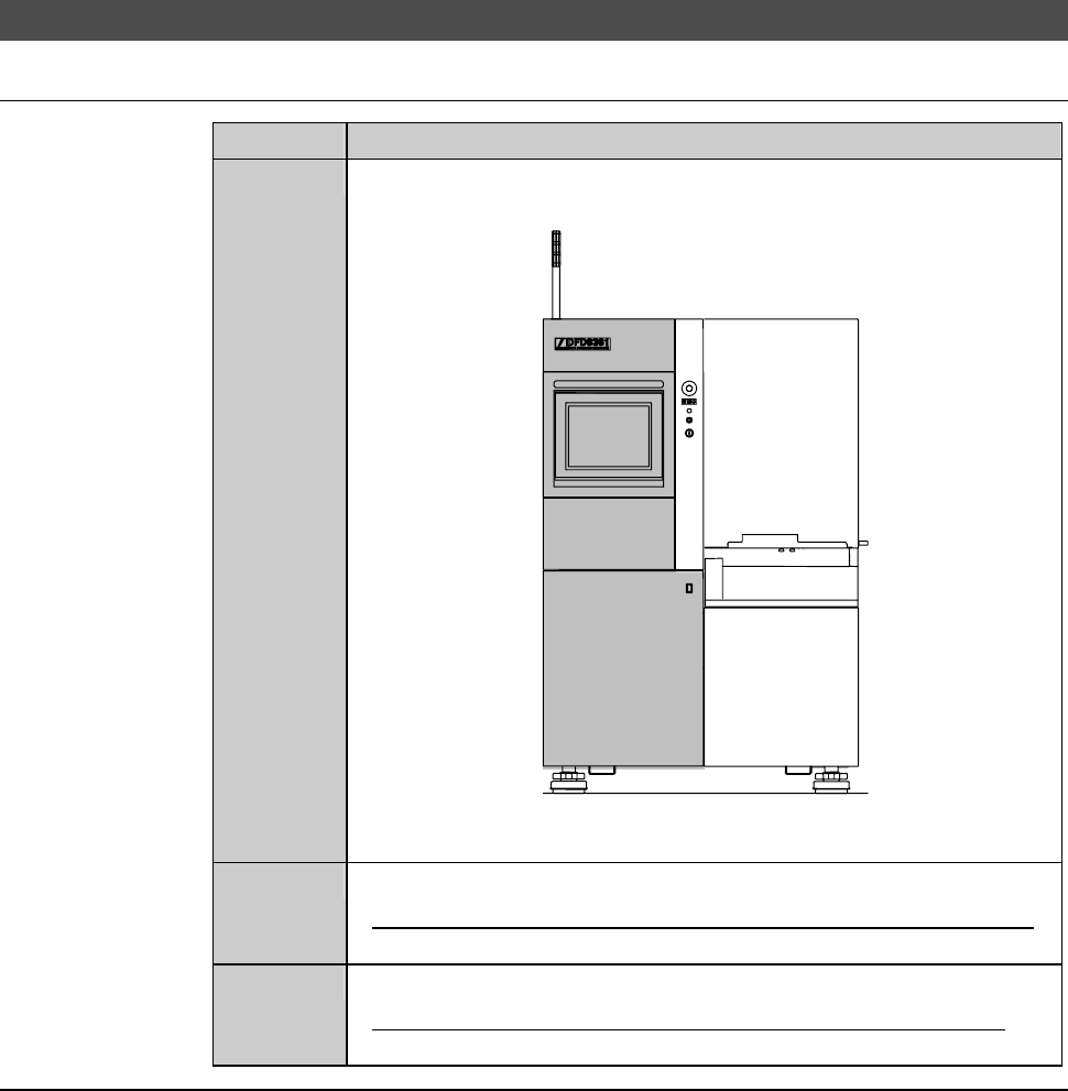
1
Remove the cover [A]. Store the removed outer cover at a
location that is far enough from the working area.
FRONT SIDE
[A]
[P]
2
Loosen the retaining screw of cover [P], and then open the cover.
- For opening procedures of the touch panel section outer cover;
see the section A-1, [Machine Outer Cover].
3
Remove the roll cover of the spindle 2 tail section.
- For the removal procedures of the Y-axis section roll cover;
See section F-1-8, [Replacing the Y-axis Section Roll Cover].
Continued in the next section.