DFD6361-Maintenance.pdf - 第594页
F-24 Procedur es for re moving the w aterproo f cap (C ontinued) Step No. Do This (Continued from the previous section.) 1 With a lint-free cloth, wipe off water or stain around the waterproof cap that is m ounted at the…
F-23
1-4-2. Removing the waterproof cap
Procedures for removing the waterproof cap
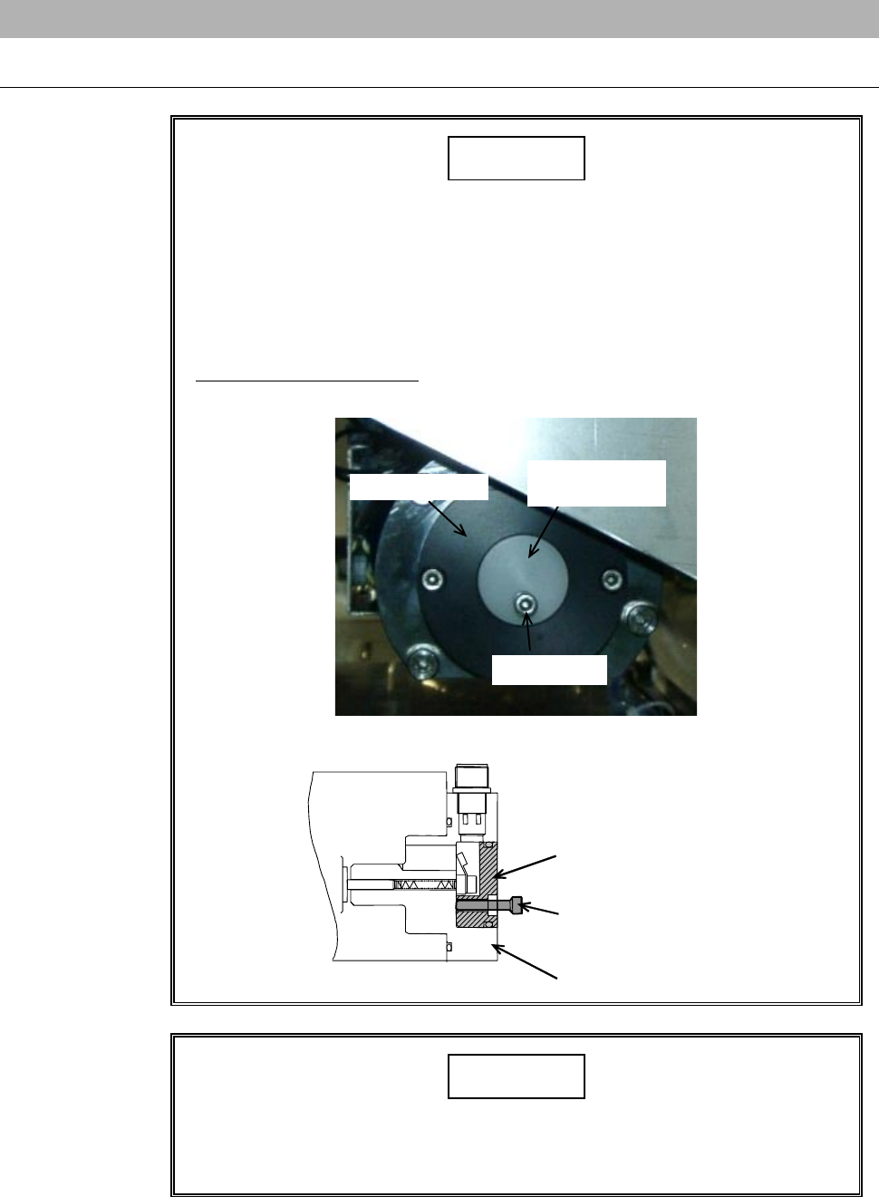
CAUTION
- There are cables within the waterproof cap. When removing the
waterproof cap, exercise care not to pull it strongly with undue
force.
- The waterproof cap (white) and spindle's back lid are made of resin.
In removal procedure of the water proof cap, if you screw a bolt
(M4×20) in it with undue force, the cap may break.
Screw in the bolt lightly and stop it when the bolt runs into the black
lid (black).
Back lid (black)
Waterproof cap
(white)
M4 × 20 bolt
ÿ
Back lid (black)
Waterproof cap
(white)
M4 × 20 bolt
NOTICE
Do not stretch or bent the spring of the carbon brush assembly. If it is
stretched or bent, this might cause abnormal performance in setup or
damage to the interior of the spindle.
F-24
Procedures for removing the waterproof cap (Continued)
Step No. Do This
(Continued from the previous section.)
1
With a lint-free cloth, wipe off water or stain around the
waterproof cap that is mounted at the rear of the spindle.
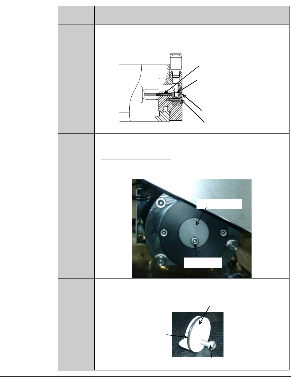
2
Remove the retaining screw of the waterproof cap.
ÿ
Retaining screw of waterproof cap
Waterproof cap
Carbon brush assembly
Carbon brush assembly
retaining screw
3
Slowly screw the M4×20 bolt into the screw hole of the
waterproof cap retaining screw.
- Screw in the bolt lightly and stop it when the bolt runs into the
black lid.
Waterproof cap
M4 × 20 bolt
4
Pull the M4×20 bolt.
- The waterproof cap comes off.
Waterproof cap
O-ring
M4 × 20 bolt
Continued in the next section.
F-25
1-4-3. Replacing the carbon brush assembly
Procedures for replacing the carbon brush assembly
NOTICE
If the terminals of the right and left cords contact with each other, the
machine fails to detect abnormality of spindle.
Mount the right and left carbon brush assemblies so that the
terminals of their cords do not contact with each other.
Step No. Do This
(Continued from the previous section.)
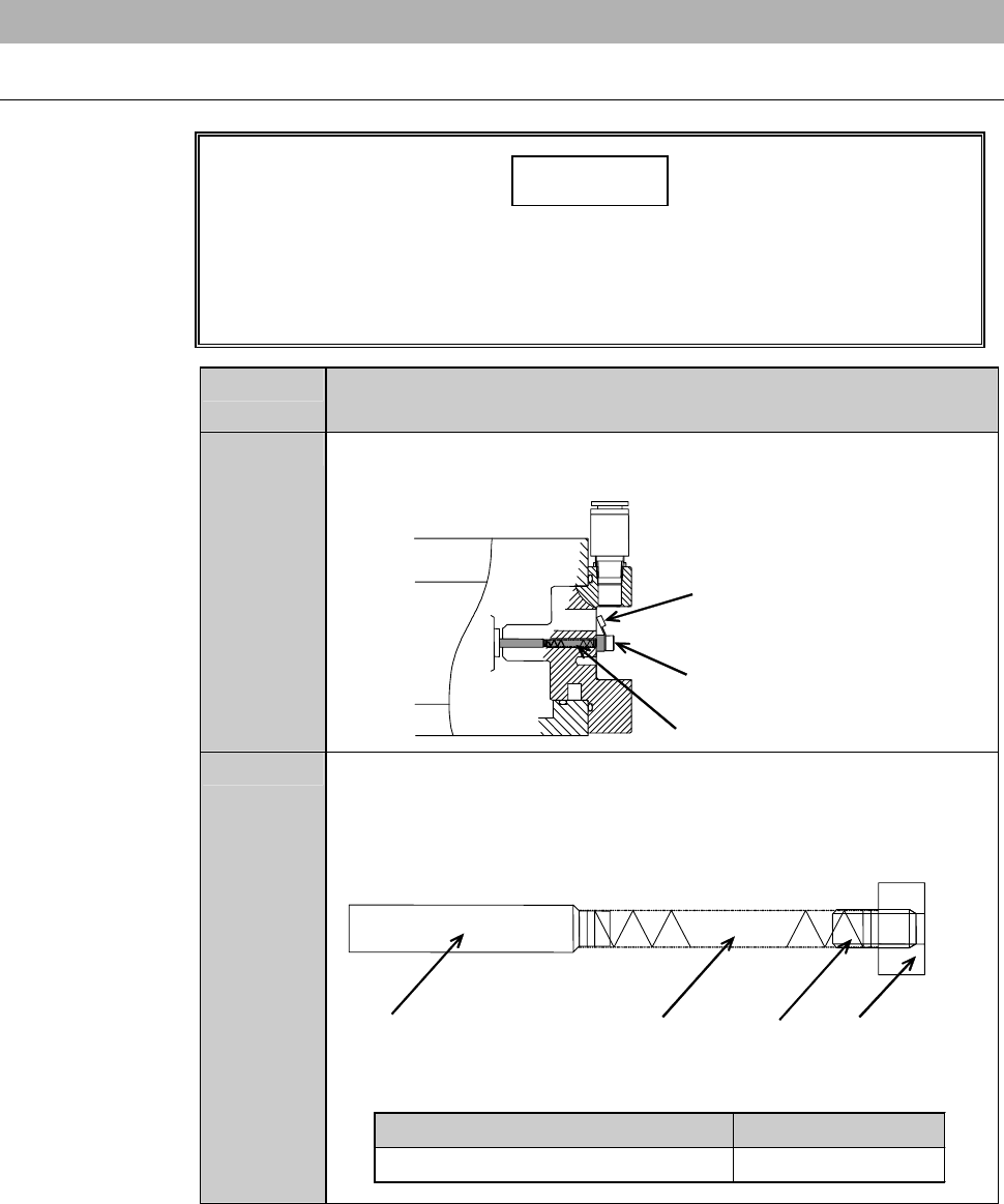
1
Disconnect the cables and retaining screw of the carbon brush
assembly.
ÿ
Carbon brush assembly
Retainin
g
screw of carbon
brush assembly
Cable
2
Take out the carbon brush assembly.
- The figure below shows the construction of the carbon brush
assembly.
- Take care not to stretch or bend the spring section.
ÿ
Carbon brush
Spring
Retaining
screw
Plate for carbon
brush
Part Name Part No.
Carbon brush assembly NCBA0015