DFD6361-Maintenance.pdf - 第597页
F-27 Procedur es for replac ing the spi ndle car bon brush ass embly (Continue d) Step No. Do This 6 With the JSUSP connector unhooked, ch eck the resistance between the carbon brus hes is lower than 20 Ω , with the test…
F-26
Procedures for replacing the carbon brush assembly (Continued)
Step No. Do This
3
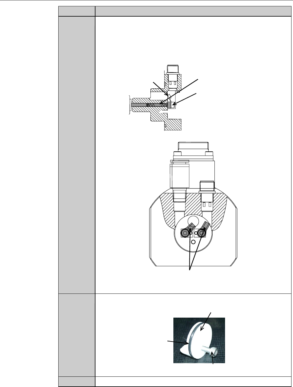
Install the new carbon brush assembly together with the cable to
the original position.
- Be careful so that the terminals of the left and right cable do nt
come into contact with each other.
Carbon brush assembly
Carbon brush assembly
mounting screw
Cable
[Cross-sectional view]
ÿ
Be careful so that the terminals
of the right and left cords do not
contact with each other.
4
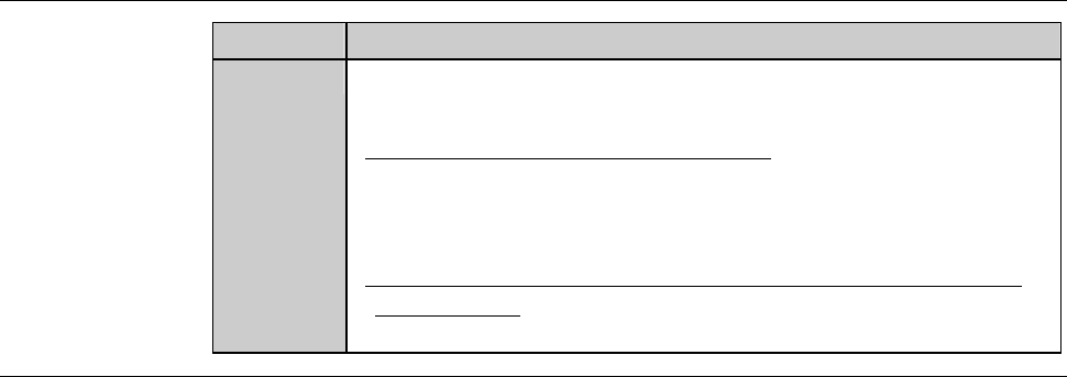
Make sure that the waterproof cap has an O-ring.
Waterproof cap
O-ring
M4 × 20 bolt
5
Reinstall the waterproof cap to the original position.
F-27
Procedures for replacing the spindle carbon brush assembly (Continued)
Step No. Do This
6
With the JSUSP connector unhooked, check the resistance
between the carbon brushes is lower than 20 Ω, with the tester.
-When the resistance is 20 Ω or higher;
It is possible that the contact between the spindle axis and
carbon brush is poor.
In this case, repeat the operations of the step 1 through 5.
-When the resistance remains at 20 Ω or higher after repeating
the operation;
Contact your nearest Disco Service Office.
Continued in the next section.
F-28
1-4-4. Completion of replacing the spindle carbon brush
Summary of this section
This section describes the procedure to complete the replacement of the
spindle carbon brush.
1-4-4-1 Completion of replacing the spindle 1 carbon brush
- Procedure to complete the replacement of spindle 1 carbon
brush, that is followed when there is maintenance space
provided at the rear side of the machine
- Procedure to complete the replacement of spindle 1 carbon
brush, that is followed when there is no maintenance space
provided at the rear side of the machine
1-4-4-2 Completion of replacing the spindle 2 carbon brush
1-4-4-1. Completion of replacing the spindle 1 carbon brush
Procedures for completion of replacing the spindle 1 carbon brush
[When there is maintenance space provided at the rear side of the
machine]
Step No. Do This
(Continued from the previous section.)
1
Reinstall the partition that has been removed.
2
Reinstall cover [R] that has been removed.
[When there is no maintenance space provided at the rear side of the
machine]
Step No. Do This
(Continued from the previous section.)
1
Reinstall the bellows at the rear of the Y-axis.
- For the bellows installation procedures;
See the section 3-5 of this chapter, [Replacing the Bellows (for
Y-Axis)].
2
Reinstall the partition (left).