DFD6361-Maintenance.pdf - 第60页
A-44 Circui t breaker secti on cover lock mec hanism When the b reaker secti on outer cover is rem oved, the bre aker section cover shows up. The circuit breaker se ction cover is locked b y the circuit break er lever an…
A-43
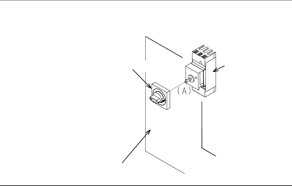
Circuit breaker lever structure
The circuit breaker lever must be placed in the "OFF" position, inserted into
the notched section [A] and then secured together with the breaker section
cover.
Breaker section cover
Breaker lever
Breaker
A-44
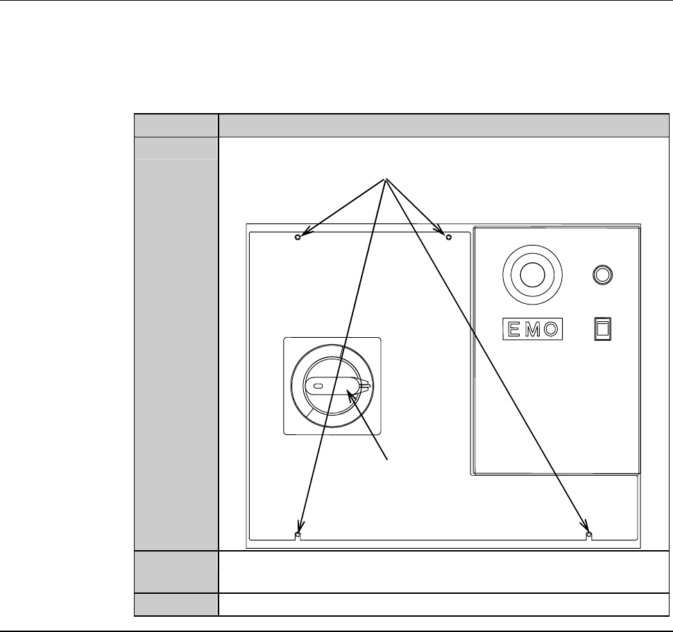
Circuit breaker section cover lock mechanism
When the breaker section outer cover is removed, the breaker section cover
shows up.
The circuit breaker section cover is locked by the circuit breaker lever and the
cover lock screws.
The procedures for releasing the cover lock are as follows:
Step No. Do This
1
Loosen the cover lock screw (M4).
Circuit breaker lever
Cover lock screw (M4)
2
Rotate the circuit breaker lever to "RESET" from "OFF" position
to unlock the lever lock.
3
Remove the breaker section cover.
A-45
4. Detection Function
Summary of this section
This section describes about the safety devices that are equipped with the
machine to secure safety.
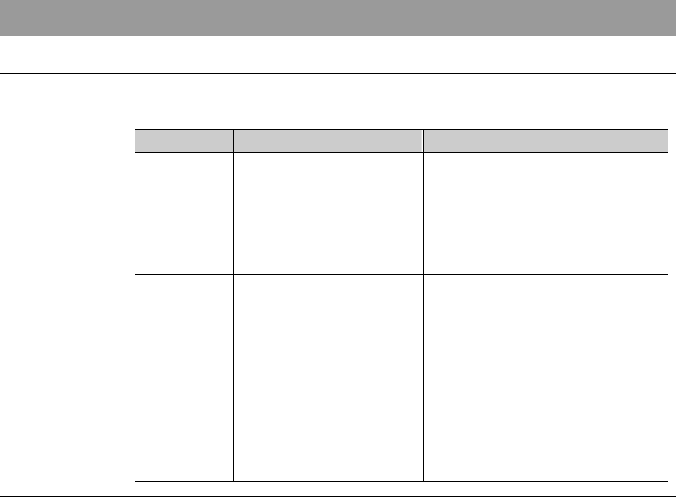
Section No. Title Contents
4-1 Personnel Protection - Location and structure of the
safety switch of the splash cover
andarmsectioncover
- Location and structure of the
lock cylinder of the splash cover
andarmsectioncover
4-2 Machine Protection - Location and structure of the air
pressure sensor
- Location and structure of the
Clean air pressure sensor
- Location and structure of the
flow rate sensor
- Location and structure of the
flow rate controller
- Location and structure of the
vacuum pressure sensor