DFD6361-Maintenance.pdf - 第600页
F-30 1-5. Re placing the Spray Tip of the Spinner Se ction Operation flow The procedure for replacing the spra y tip of the spinner section nozzle axis consists of the f ollowing steps. Note that the spinne r atomizing n…
F-29
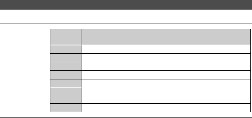
1-4-4-2. Completion of replacing the spindle 2 carbon brush
Procedures for completion of replacing the spindle 2 carbon brush
Step No. Do This
(Continued from the previous section.)
1
Reinstall the Y-axis section roll cover that has been removed.
2
Close the cover [P] and secure it with the retaining screws.
3
Reinstall the cover [A].
4
Open the facility main valve of air.
5
Turn ON the facility power source.
6
Open the lock of the circuit breaker lever and turn ON the circuit
breaker.
7
Insert the key into the main switch and turn ON the main switch.
F-30
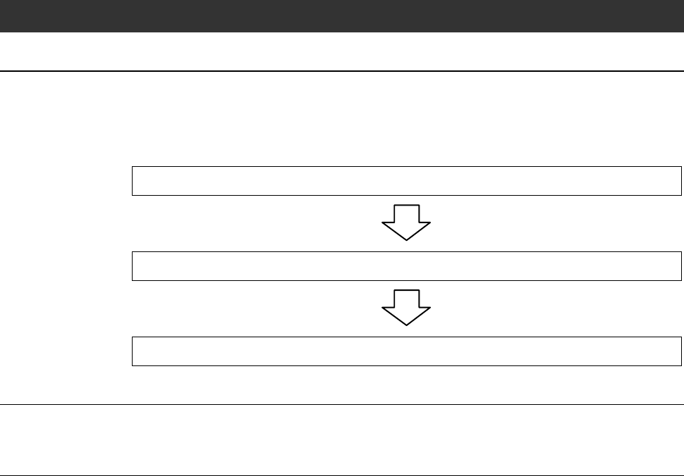
1-5. Replacing the Spray Tip of the Spinner Section
Operation flow
The procedure for replacing the spray tip of the spinner section nozzle axis
consists of the following steps.
Note that the spinner atomizing nozzle [optional accessory] has no
consumable parts.
1-5-1 Preparation of replacing the spray tip
1-5-2 Replacing the spray tip
1-5-3 Completion of replacing the spray tip
Before replacement
Have on hand the following items for replacing.
- Wrench
F-31
1-5-1. Preparation of replacing the spray tip
Procedures for preparation of replacing the spray tip
WARNING
- In the digital I/O check procedures, touch panel buttons except for
function buttons are inoperative.
Even if, for example, you press the <Cut Water> button, the wheel
coolant supply does not shut off.
The personnel who perform the digital I/O checkout must bear this
in mind and exercise due care to ensure safety.
- In the digital I/O check procedures, the operation command for
solenoid valves and etc. can be forcibly turned ON and OFF by the
function buttons. In some cases, therefore, a cylinder may be
invoked to operate.
Ensure that no person other than the maintenance personnel
touches the machine during this procedure.
- If any touch panel control is inadvertently activated during
maintenance or inspection, unexpected machine operation may
cause death or serious injury.
While you don't use the touch panel, press the Disco's logo button
located at the upper left of the screen in order to lock up and
deactivate the touch panel.
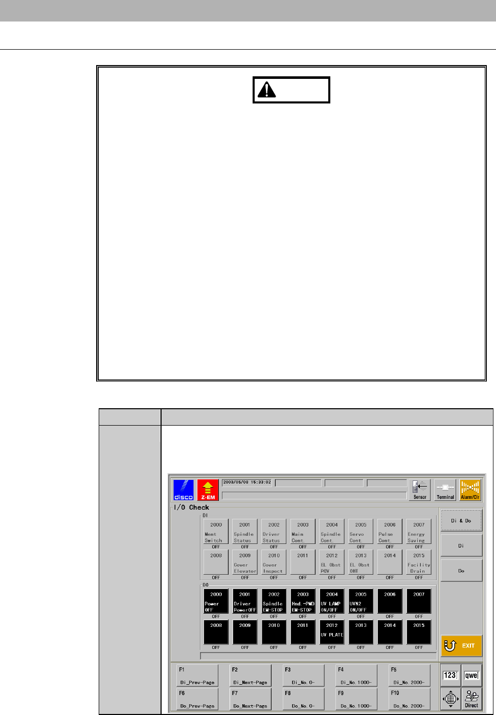
Step No. Do This
1
From the ENGINEERING MAINTENANCE screen [screen 7.0],
press the <F3> button.
- The I/O CHECK screen then appears.