DFD6361-Maintenance.pdf - 第610页
F-40 1-7. Repla cing the Pad of the Lo wer Arm Section Before replac ement Have on hand the following items for replacing. - Phillips screwdrive r Procedur es for replaci ng the pad of the low er arm secti on W ARNING - …
F-39
Procedures for replacing the pad of the upper arm section (Continued)
Step No. Do This
8
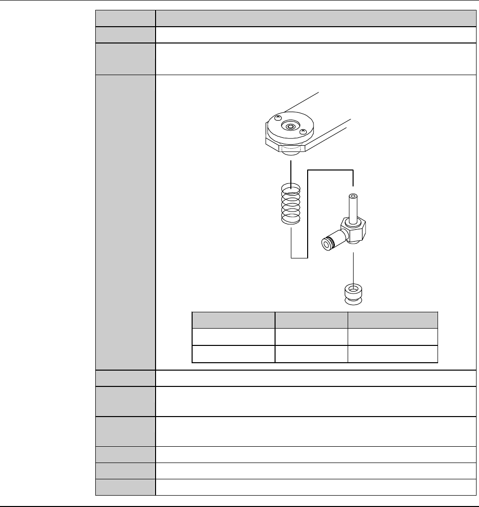
Remove the joint from the pad plate.
9
Remove the pad from the joint.
- To remove the pad, pull it.
10
Replace the pad with a new one.
Spring
Joint
Pad
Model Part Name Part No.
DFD6351
Pad (φ 8)
MOELT080--A
DFD6361
Pad (φ 15)
MOJET019
11
Reassemble the pad plate.
12
Repeat the steps 7 through 11 to replace all of four pads to the
new ones.
13
Being careful with the orientation of the pad plate, reinstall it to
the arm.
14
Connect the tube.
15
Close the front arm section cover.
16
Press the <System Initial> button to effect system initialization.
F-40
1-7. Replacing the Pad of the Lower Arm Section
Before replacement
Have on hand the following items for replacing.
- Phillips screwdriver
Procedures for replacing the pad of the lower arm section
WARNING
- When you perform the procedure set forth in this section, you have
to place your hands in the X-axis and transport drive section. If
other person touches the machine during maintenance, your fingers
or hands may be caught or cut off.
Ensure that no other person touches the machine while perform
maintenance.
- If any touch panel control is inadvertently activated during
maintenance or inspection, unexpected machine operation may
cause death or serious injury.
While you don't use the touch panel, press the Disco's logo button
located at the upper left of the screen in order to lock up and
deactivate the touch panel.
Step No. Do This
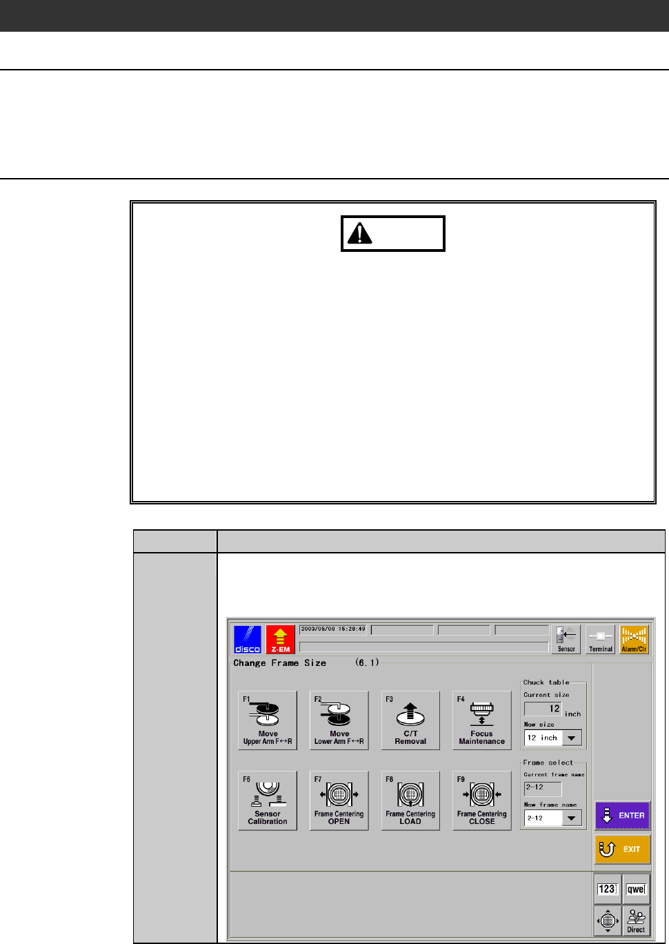
1
From the MACHINE MAINTENANCE screen [screen 6.0],
press the <F1> button.
- The CHANGE FRAME SIZE screen [screen 6.1] then appears.
F-41
Procedures for replacing the pad of the lower arm section (Continued)
Step No. Do This
2
From the CHANGE FRAME SIZE screen [screen 6.1], press the
<F2> button.
- The lower arm moves to above the chuck table.
3
Verify that the lower arm is stopped completely.
4
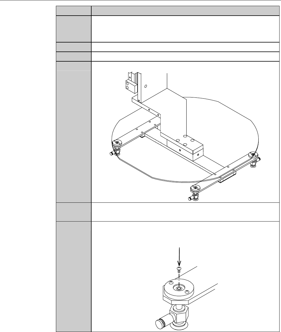
Open the front arm section cover.
5
Remove the tube.
6
Slide the pad plate toward outside, then remove them.
- Check the orientation of the pad late for reinstallation.
7
Remove the retaining screw of the joint.
Retaining screw
(Cross-shaped recess screw)