DFD6361-Maintenance.pdf - 第626页
F-56 2-1-2. Re placing t he flow rate sensor Procedur es for replaci ng the flow r ate sensor CAUTION The flow meter pipi ng and sw itch harnesses are att ached to the bracket. W hen you r emove th e bracket, exerci se c…
F-55
Procedures for removing the machine outer cover (Continued)
Step No. Do This
5
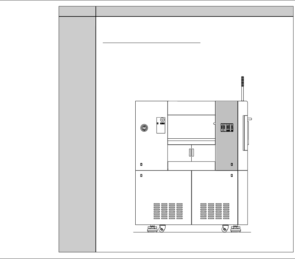
Remove the cover [U]. Then store it sufficiently away from the
working area.
- For the cover removal procedure;
See the section B-2-2, [Removing the Machine Outer Cover,
Monitor and Status Indicator] of Installation Manual.
ÿ
[U]
LEFT SIDE
Continued in the next section.
F-56
2-1-2. Replacing the flow rate sensor
Procedures for replacing the flow rate sensor
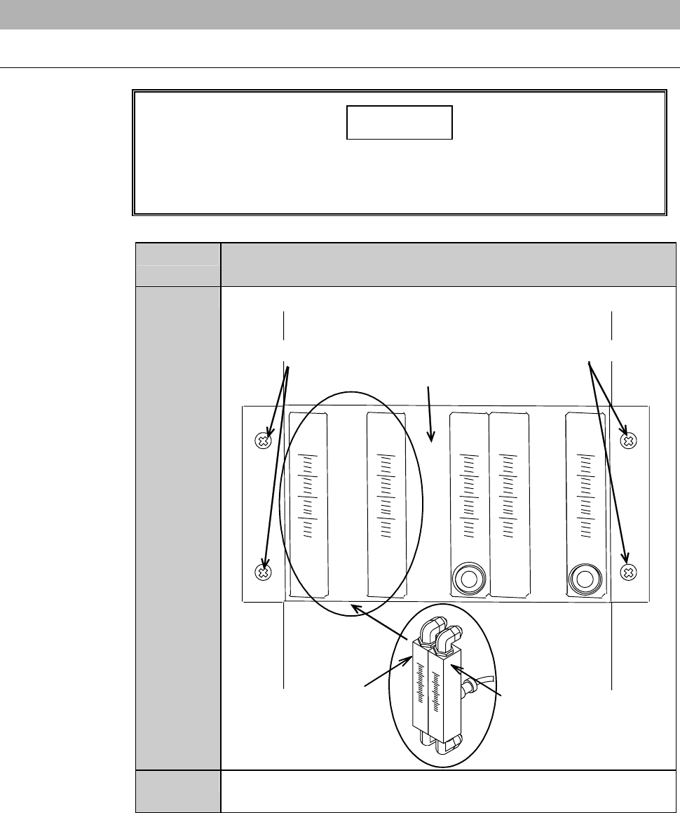
CAUTION
The flowmeter piping and switch harnesses are attached to the
bracket. When you remove the bracket, exercise care not to pull it
strongly with undue force.
Step No. Do This
(Continued from the previous section)
1
Unscrew the retaining screws of the bracket.
Retaining screws Retaining screws
Bracket
Spindle 1 coolant water
flow rate sensor (Z2)
Spindle 2 coolant water
flow rate sensor (Z1)
2
Remove the bracket slowly, being careful not to unplug the
junctions behind the bracket.
F-57
Procedures for replacing the flow rate sensor (Continued)
Step No. Do This
3
Disconnect the spindle coolant water piping and joint.
4
Unscrew the retaining screw of the spindle coolant water flow
rate sensor.
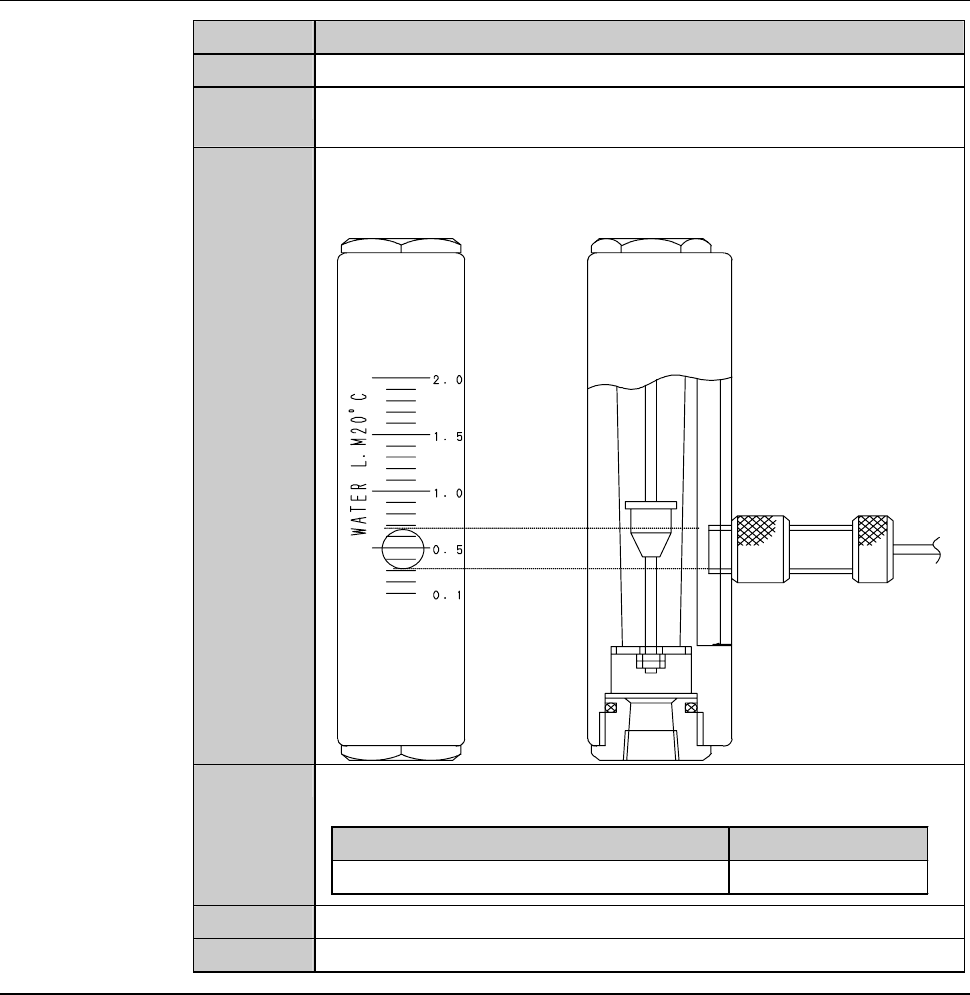
5
Adjust the setting value of the new flow rate sensor to a specified
level.
- In the example below, the check value is set to 0.5 L/min.
6
Install a new spindle coolant water flow rate sensor to the
bracket.
Part Name Part No.
Flow checker MOHEH058--C
7
Reconnect the spindle coolant water flow rate sensor piping.
8
Reinstall the bracket in its original position.
Continued in the next section.