DFD6361-Maintenance.pdf - 第627页
F-57 Procedur es for replaci ng the flow r ate sensor ( Continued) Step No. Do This 3 Disconnect the spindle coolant water piping and joint. 4 Unscrew the ret aining screw of the spindle coolant water flow rate sensor. 5…
F-56
2-1-2. Replacing the flow rate sensor
Procedures for replacing the flow rate sensor
CAUTION
The flowmeter piping and switch harnesses are attached to the
bracket. When you remove the bracket, exercise care not to pull it
strongly with undue force.
Step No. Do This
(Continued from the previous section)
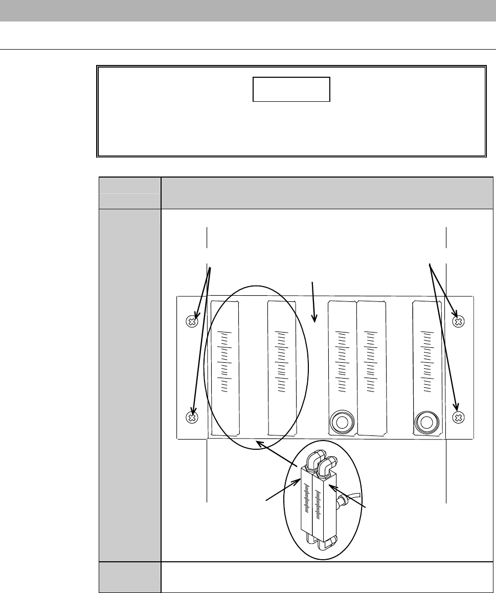
1
Unscrew the retaining screws of the bracket.
Retaining screws Retaining screws
Bracket
Spindle 1 coolant water
flow rate sensor (Z2)
Spindle 2 coolant water
flow rate sensor (Z1)
2
Remove the bracket slowly, being careful not to unplug the
junctions behind the bracket.
F-57
Procedures for replacing the flow rate sensor (Continued)
Step No. Do This
3
Disconnect the spindle coolant water piping and joint.
4
Unscrew the retaining screw of the spindle coolant water flow
rate sensor.
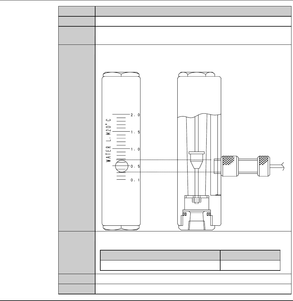
5
Adjust the setting value of the new flow rate sensor to a specified
level.
- In the example below, the check value is set to 0.5 L/min.
6
Install a new spindle coolant water flow rate sensor to the
bracket.
Part Name Part No.
Flow checker MOHEH058--C
7
Reconnect the spindle coolant water flow rate sensor piping.
8
Reinstall the bracket in its original position.
Continued in the next section.
F-58
2-1-3. Completion of replacing the flow rate sensor
Procedures for completion of replacing the flow rate sensor
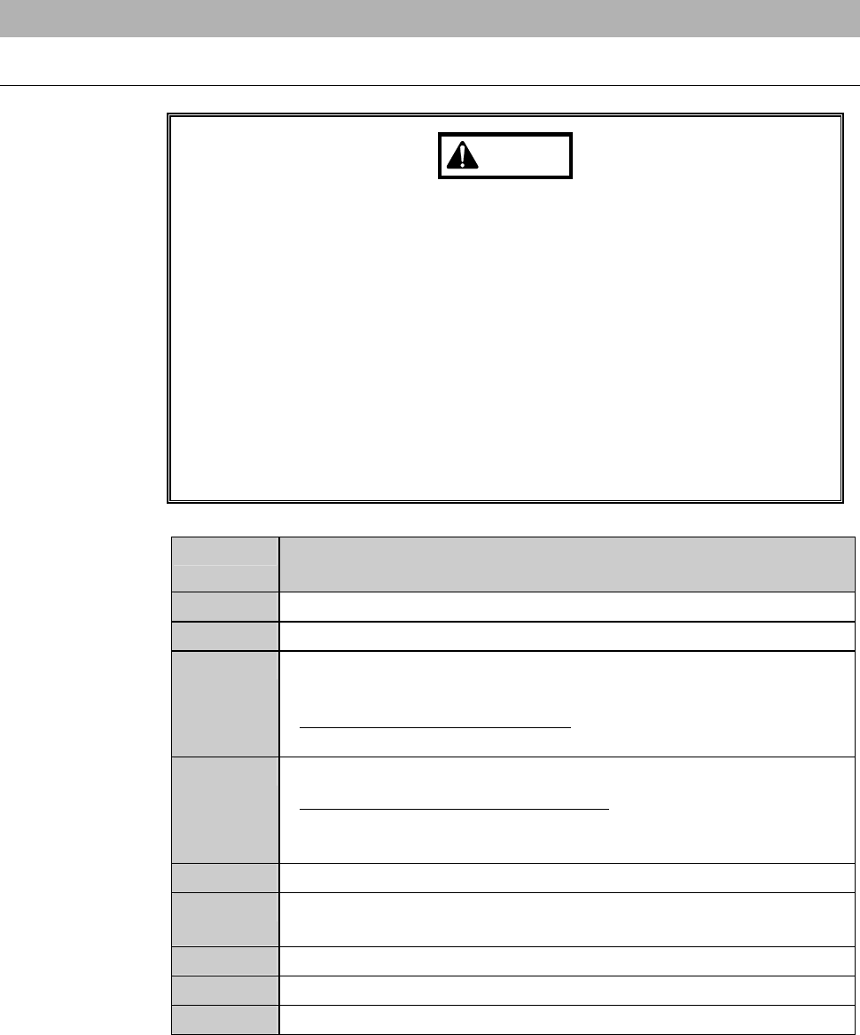
WARNING
- If you operate the machine while the machine interior or floor is wet
with water, you may receive electric shock that could result in
serious injury or death.
If the machine or floor is wet with water, do not turn ON the facility
power source until it dries.
- Upon the completion of replacement, release the spindle coolant
water to make sure that no water leakage occurs. If you operate the
machine while the machine interior or floor is wet with water, you
may receive electric shock that could result in serious injury or
death.
If any water leakage is found, shut off the facility power supply and
then properly install the piping.
Step No. Do This
(Continued from the previous section)
1
Verify that there is no water leakage inside the machine.
2
Open the spindle coolant water supply line main valve.
3
Check that there is no water leakage in the piping joint for the
newly installed spindle coolant water flow rate sensor.
- When the water leakage occurs;
Repeat the steps 2-1-1 through 2-1-3 of this chapter.
4
Reinstall the cover [U] in its original position.
- For the cover installation procedure;
See the section B-1-6, [Mounting Machine Outer Covers] of
Installation Manual.
5
Turn ON the facility power source.
6
Open the circuit breaker lever lockout and turn ON the circuit
breaker.
7
Insert the key into the main switch and turn ON the main switch.
8
Press the <System Initial> button to effect system initialization.
9
Adjust the flow rate.