DFD6361-Maintenance.pdf - 第635页
F-65 Procedur es for re placing the s olenoid v alve (C ontinued) Step No. Do This 7 Reinstall the removed joint, piping and wiring in their original positions. 8 Verify that there is no water lea kage inside the machine…
F-64
Procedures for replacing the solenoid valve (Continued)
Step No. Do This
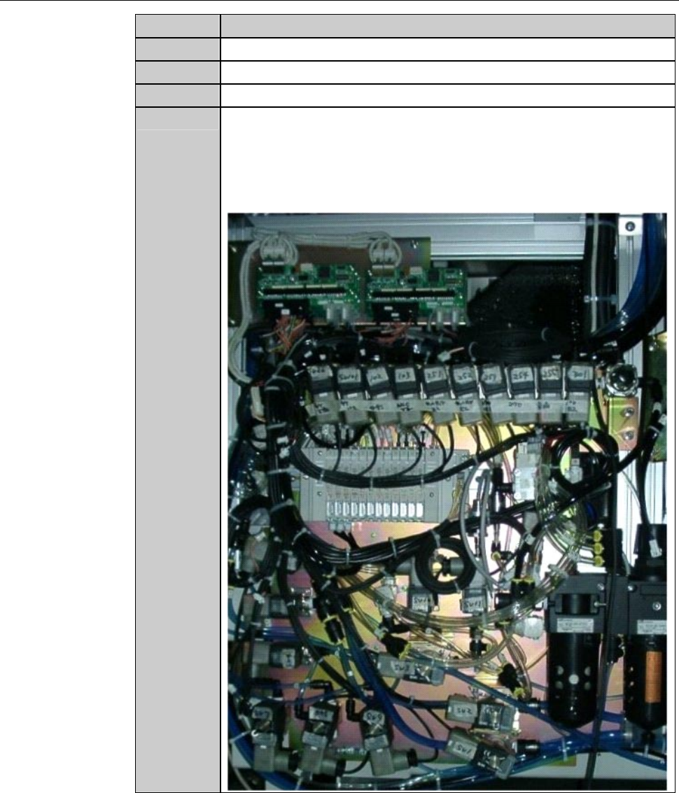
3
Remove the solenoid valve mounting screws.
4
Remove the solenoid valve.
5
Remove the solenoid valve joint.
6
Replace the solenoid valve with a new one.
- There are various types of solenoid valve. For their part
numbers, refer to the water/air piping diagram and parts list in
the chapter E, [Water and Air Piping] of the Technical
Reference.
F-65
Procedures for replacing the solenoid valve (Continued)
Step No.
Do This
7
Reinstall the removed joint, piping and wiring in their original
positions.
8
Verify that there is no water leakage inside the machine.
9
Reinstall the covers [A] and [B] in their original positions.
- For the cover installation procedure;
See the section B-1-6, [Mounting Machine Outer Covers] of
Installation Manual.
Continued in the next section.
F-66
2-2-3. Completion of replacing the solenoid valve
Procedures for completion of replacing the solenoid valve
WARNING
- If you operate the machine while the machine interior or floor is wet
with water, you may receive electric shock that could result in
serious injury or death.
If the machine or floor is wet with water, do not turn ON the facility
power source until it dries.
- Upon the completion of replacement, turn ON and OFF the newly
installed solenoid valve to check that no leakage of water or air
occurs. If you operate the machine while the machine interior or
floor is wet with water, you may receive electric shock that could
result in serious injury or death.
If any water leakage is found, shut off the facility power supply and
then properly install the piping.
Step No. Do This
(Continued from the previous section)
1
Turn ON the facility power source.
2
Open the facility main valves of the supply lines for the air,
wheel coolant water and spindle coolant water.
3
Open the circuit breaker lever lockout and turn ON the circuit
breaker.
4
Insert the key into the main switch and turn ON the main switch.
5
Call up the I/O CHECK screen, and turn ON and OFF the newly
installed solenoid vale to check for water leakage in the solenoid
valve piping joint.
- When the water leakage occurs;
Turn OFF the power of the machine immediately. Then repeat
the steps 2-2-1 through 2-2-3 of this chapter.
- About the I/O CHECK screen,
see the section C-4-1, [Digital I/O Check].